Sistem CM1126B-P Terbenam Boardcon pada Modul
Spesifikasi
| Ciri | Spesifikasi |
| CPU | Korteks-A53 empat teras |
| DDR | 2GB LPDDR4 (sehingga 4GB) |
| eMMC FLASH | 8GB (sehingga 256GB) |
| kuasa | DC 3.3V |
| MIPI DSI | 4-Lorong |
| I2S | 4-CH |
| MIPI CSI | 2-CH 4-Lorong |
| LCD RGB | 24bit |
| Kamera | 1-CH(DVP) dan 2-CH(CSI) |
| USB | 2-CH (USB HOST 2.0 and OTG 2.0) |
| Ethernet | 1000M GMAC |
| SDMMC | 2-CH |
| I2C | 5-CH |
| SPI | 2-CH |
| UART | 5-CH, 1-CH(DEBUG) |
| PWM | 11-CH |
| ADC DALAM | 4-CH |
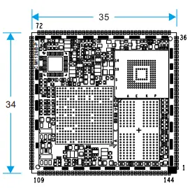
| Dimensi Papan | 34 x 35mm |
pengenalan
Mengenai Manual ini
Manual ini bertujuan untuk memberikan pengguna lebihview of the board and its benefits, complete feature specifications, and setup procedures. It contains important safety information as well.
Maklum Balas dan Kemas Kini Manual ini
Untuk membantu pelanggan kami memanfaatkan produk kami sepenuhnya, kami sentiasa menyediakan sumber tambahan dan dikemas kini di Boardcon webtapak (www.boardcon.com, www.armdesigner.com). Ini termasuk manual, nota aplikasi, pengaturcaraan examples, dan perisian serta perkakasan yang dikemas kini. Daftar masuk secara berkala untuk melihat perkara baharu! Apabila kami mengutamakan kerja pada sumber yang dikemas kini ini, maklum balas daripada pelanggan adalah pengaruh nombor satu, Jika anda mempunyai soalan, komen atau kebimbangan tentang produk atau projek anda, sila tidak teragak-agak untuk menghubungi kami di support@armdesigner.com.
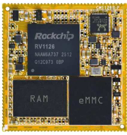
CM1126B-P Introduction
Ringkasan
The CM1126B-P system-on-module is equipped with Rockchip’s RV1126B-P, built with a quad-core Cortex-A53, 3.0 TOPs NPU, and RISC-V MCU. It is designed specifically for the IPC/CVR devices, AI Camera devices, intelligent interactive devices, and mini robots. High-performance and low-power solutions can help customers introduce new technologies more quickly and enhance the overall solution efficiency. The smallest size can be put on a 38board. Following the hardware revision from CM1126 (V1) to CM1126B-P (V2), where the SoC is updated to the RV1126B-P, the Reset & OTG_VBUS signals and the WIFI/BT module’s GPIO voltage mesti beroperasi pada tahap logik 3.3V.
Ciri-ciri
Mikropemproses
- Quad-core Cortex-A53 sehingga 1.6GHz
- 32KB I-cache dan 32KB D-cache untuk setiap teras, 512KB L3 cache
- 3.0 TOPS Unit Proses Neural
- RISC-V MCU to support 250ms fast boot
- ISP maksimum 12M
Organisasi Memori
- LPDDR4 RAM sehingga 4GB
- eMMC sehingga 256GB
- SPI Flash sehingga 8MB
Penyahkod/Pengekod Video
- Menyokong penyahkod/enkod video sehingga 4K@30fps
- Menyokong penyahkodan masa nyata H.264/265
- Menyokong pengekodan video UHD H.264/265 masa nyata
- Saiz gambar sehingga 8192×8192
Subsistem Paparan
- Output Video
- Menyokong 4 lorong MIPI DSI sehingga 2560×1440@60fps
- Supports 24-bit RGB parallel output
- Imej masuk
- Supports up to 16-bit DVP interface
- Menyokong antara muka 2ch MIPI CSI 4lanes
I2S/PCM/ AC97
- Tiga antara muka I2S/PCM
- Sokong susunan mikrofon Sehingga antara muka PDM/TDM 8ch
- Menyokong output audio PWM
USB dan PCIE
- Dua antara muka USB 2.0
- One USB 2.0 OTG and one 2.0 USB host
Ethernet
- RTL8211F di atas kapal
- Sokongan 10/100/1000M
I2C
- Sehingga lima I2C
- Menyokong mod standard dan mod pantas (sehingga 400kbit/s)
SDIO
- Menyokong protokol 2CH SDIO 3.0
SPI
- Sehingga dua pengawal SPI,
- Antara muka siri segerak dupleks penuh
UART
- Menyokong sehingga 6 UART
- UART2 dengan 2 wayar untuk alat nyahpepijat
- Embedded two 664-byte FIFOs
- Sokong mod kawalan aliran automatik untuk UART0/1/3/4/5
ADC
- Sehingga empat saluran ADC
- resolusi 12-bit
- Voltage julat input antara 0V hingga 1.8V
- Menyokong sehingga 1MS/ssampkadar ling
PWM
- 11 PWM pada cip dengan operasi berasaskan gangguan
- Support 32-bit time/counter facility
- Pilihan IR pada PWM3/7
Unit kuasa
- Kuasa Diskret di atas kapal
- Input 3.3V tunggal
Rajah Blok CM1126B-P
RV1126B-P Block Diagram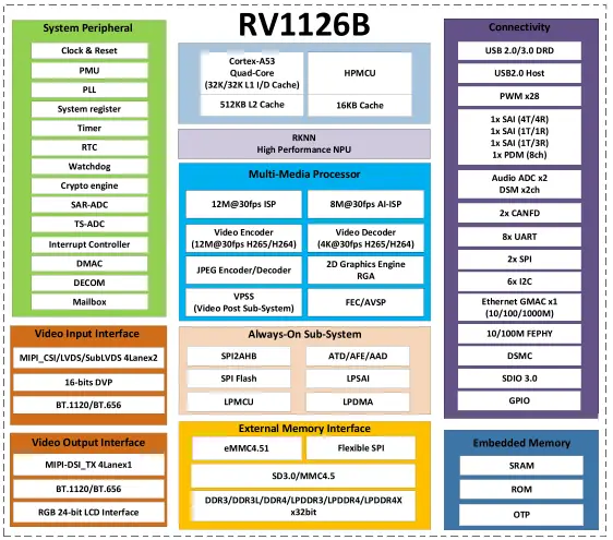
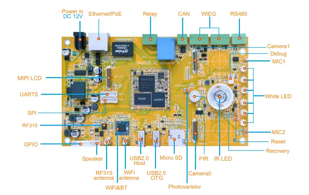
Development board (Idea1126) Block Diagram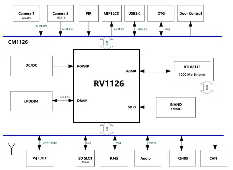
Dimensi PCB CM1126B-P
Definisi Pin CM1126B-P
| Pin | isyarat | Penerangan atau fungsi | siri GPIO | IO Voltage |
| 1 | LCDC_D19_3V3 | I2S1_MCLK_M2/CIF_D15_M1 | GPIO2_C7_d | 3.3V |
| 2 | LCDC_D20_3V3 | I2S1_SDO_M2/CIF_VS_M1 | GPIO2_D0_d | 3.3V |
| 3 | LCDC_D21_3V3 | I2S1_SCLK_M2/CIF_CLKO_M1 | GPIO2_D1_d | 3.3V |
| 4 | LCDC_D22_3V3 | I2S1_LRCK_M2/CIF_CKIN_M1 | GPIO2_D2_d | 3.3V |
| 5 | LCDC_D23_3V3 | I2S1_SDI_M2/CIF_HS_M1 | GPIO2_D3_d | 3.3V |
| 6 | GND | tanah | 0V | |
| 7 | GPIO1_D1 | UART1_RX_M1/I2C5_SDA_M2 | GPIO1_D1_d | 3.3V(V2) |
| 8 | BT_WAKE | SPI0_CS1n_M0 | GPIO0_A4_u | 3.3V(V2) |
| 9 | WIFI_REG_ON | SPI0_MOSI_M0 | GPIO0_A6_d | 3.3V(V2) |
| 10 | BT_RST | SPI0_MISO_M0 | GPIO0_A7_d | 3.3V(V2) |
| 11 | WIFI_WAKE_HOST | SPI0_CLK_M0 | GPIO0_B0_d | 3.3V(V2) |
| 12 | BT_WAKE_HOST | SPI0_CS0n_M0 | GPIO0_A5_u | 3.3V(V2) |
| 13 | PWM7_IR_M0_3V3 | GPIO0_B1_d | 3.3V | |
| 14 | PWM6_M0_3V3 | TSADC_SHUT_M1 | GPIO0_B2_d | 3.3V |
| 15 | UART2_TX_3V3 | Untuk nyahpepijat | GPIO3_A2_u | 3.3V |
| 16 | UART2_RX_3V3 | Untuk nyahpepijat | GPIO3_A3_u | 3.3V |
| 17 | I2S0_MCLK_M0_3V
3 |
GPIO3_D2_d | 3.3V | |
| 18 | I2S0_SCLK_TX_M0
_3V3 |
ACODEC_DAC_CLK | GPIO3_D0_d | 3.3V |
| 19 | I2S0_SDI3_M0_3V3 | PDM_SDI3_M0 /
ACODEC_ADC_DATA |
GPIO3_D7_d | 3.3V |
| 20 | I2S0_SDO0_M0_3V
3 |
ACODEC_DAC_DATAR
/APWM_R_M1/ADSM_LP |
GPIO3_D5_d | 3.3V |
| Pin | isyarat | Penerangan atau fungsi | siri GPIO | IO Voltage |
| 21 | I2S0_LRCK_TX_M0
_3V3 |
ACODEC_DAC_SYNC
/APWM_L_M1/ADSM_LN |
GPIO3_D3_d | 3.3V |
| 22 | PDM_SDI1_3V3 | I2S0_SDO3_SDI1_M0/I2C4SDA | GPIO4_A1_d | 3.3V |
| 23 | PDM_CLK1_3V3 | I2S0_SCK_RX_M0 | GPIO3_D1_d | 3.3V |
| 24 | PDM_SDI2_3V3 | I2S0_SDO2_SDI2_M0/I2C4SCL | GPIO4_A0_d | 3.3V |
| 25 | PDM_SDI0_3V3 | I2S0_SDI0_M0 | GPIO3_D6_d | 3.3V |
| 26 | PDM_CLK_3V3 | I2S0_LRCK_RX_M0 | GPIO3_D4_d | 3.3V |
| 27 | I2C2_SDA_3V3 | PWM5_M0 | GPIO0_C3_d | 3.3V |
| 28 | I2C2_SCL_3V3 | PWM4_M0 | GPIO0_C2_d | 3.3V |
| 29 | USB_HOST_DP | 1.8V | ||
| 30 | USB_HOST_DM | 1.8V | ||
| 31 | GND | tanah | 0V | |
| 32 | OTG_DP | Can be used for download | 1.8V | |
| 33 | OTG_DM | Can be used for download | 1.8V | |
| 34 | OTG_DET(V2) | OTG VBUS DET IN | 3.3V(V2) | |
| 35 | OTG_ID | 1.8V | ||
| 36 | SPI0_CS1n_M1 | I2S1_MCK_M1/UART4_TX_M2 | GPIO1_D5_d | 1.8V |
| 37 | VCC3V3_SYS | Input Kuasa Utama 3.3V | 3.3V | |
| 38 | VCC3V3_SYS | Input Kuasa Utama 3.3V | 3.3V | |
| 39 | USB_CTRL_3V3 | GPIO0_C1_d | 3.3V | |
| 40 | SDMMC0_DET | Mesti digunakan untuk Kad SD | GPIO0_A3_u | 3.3V(V2) |
| 41 | CLKO_32K | Keluaran jam RTC | GPIO0_A2_u | 3.3V(V2) |
| 42 | nRESET | Tetapkan semula input kunci | 3.3V(V2) | |
| 43 | MIPI_CSI_RX0_CL
KP |
Input MIPI CSI0 atau LVDS0 | 1.8V | |
| 44 | MIPI_CSI_RX0_CL
KN |
Input MIPI CSI0 atau LVDS0 | 1.8V | |
| 45 | MIPI_CSI_RX0_D2
P |
Input MIPI CSI0 atau LVDS0 | 1.8V | |
| 46 | MIPI_CSI_RX0_D2
N |
Input MIPI CSI0 atau LVDS0 | 1.8V | |
| 47 | MIPI_CSI_RX0_D3
P |
Input MIPI CSI0 atau LVDS0 | 1.8V | |
| 48 | MIPI_CSI_RX0_D3
N |
Input MIPI CSI0 atau LVDS0 | 1.8V | |
| 49 | MIPI_CSI_RX0_D1
P |
Input MIPI CSI0 atau LVDS0 | 1.8V | |
| 50 | MIPI_CSI_RX0_D1
N |
Input MIPI CSI0 atau LVDS0 | 1.8V | |
| 51 | MIPI_CSI_RX0_D0
P |
Input MIPI CSI0 atau LVDS0 | 1.8V |
| Pin | isyarat | Penerangan atau fungsi | siri GPIO | IO Voltage |
| 52 | MIPI_CSI_RX0_D0
N |
Input MIPI CSI0 atau LVDS0 | 1.8V | |
| 53 | GND | tanah | 0V | |
| 54 | MIPI_CSI_RX1_D3
P |
Input MIPI CSI1 atau LVDS1 | 1.8V | |
| 55 | MIPI_CSI_RX1_D3
N |
Input MIPI CSI1 atau LVDS1 | 1.8V | |
| 56 | MIPI_CSI_RX1_CL
KP |
Input MIPI CSI1 atau LVDS1 | 1.8V | |
| 57 | MIPI_CSI_RX1_CL
KN |
Input MIPI CSI1 atau LVDS1 | 1.8V | |
| 58 | MIPI_CSI_RX1_D2
P |
Input MIPI CSI1 atau LVDS1 | 1.8V | |
| 59 | MIPI_CSI_RX1_D2
N |
Input MIPI CSI1 atau LVDS1 | 1.8V | |
| 60 | MIPI_CSI_RX1_D1
P |
Input MIPI CSI1 atau LVDS1 | 1.8V | |
| 61 | MIPI_CSI_RX1_D1
N |
Input MIPI CSI1 atau LVDS1 | 1.8V | |
| 62 | MIPI_CSI_RX1_D0
P |
Input MIPI CSI1 atau LVDS1 | 1.8V | |
| 63 | MIPI_CSI_RX1_D0
N |
Input MIPI CSI1 atau LVDS1 | 1.8V | |
| 64 | SDMMC0_D3_3V3 | UART3_TX_M1 | GPIO1_A7_u | 3.3V |
| 65 | SDMMC0_D2_3V3 | UART3_RX_M1 | GPIO1_A6_u | 3.3V |
| 66 | SDMMC0_D1_3V3 | UART2_TX_M0 | GPIO1_A5_u | 3.3V |
| 67 | SDMMC0_D0_3V3 | UART2_RX_M0 | GPIO1_A4_u | 3.3V |
| 68 | SDMMC0_CMD_3V
3 |
UART3_CTSn_M1 | GPIO1_B1_u | 3.3V |
| 69 | SDMMC0_CLK_3V3 | UART3_RTSn_M1 | GPIO1_B0_u | 3.3V |
| 70 | GND | tanah | 0V | |
| 71 | LED1/CFG_LDO0 | LED PAUTAN Ethernet | 3.3V | |
| 72 | LED2/CFG_LDO1 | LED KELAJUAN Ethernet | 3.3V | |
| 73 | MDI0 + | Isyarat MDI Ethernet | 1.8V | |
| 74 | MDI0- | Isyarat MDI Ethernet | 1.8V | |
| 75 | MDI1 + | Isyarat MDI Ethernet | 1.8V | |
| 76 | MDI1- | Isyarat MDI Ethernet | 1.8V | |
| 77 | MDI2 + | Isyarat MDI Ethernet | 1.8V | |
| 78 | MDI2- | Isyarat MDI Ethernet | 1.8V | |
| 79 | MDI3 + | Isyarat MDI Ethernet | 1.8V | |
| 80 | MDI3- | Isyarat MDI Ethernet | 1.8V | |
| 81 | I2C1_SCL | UART4_CTSn_M2 | GPIO1_D3_u | 1.8V |
| Pin | isyarat | Penerangan atau fungsi | siri GPIO | IO Voltage |
| 82 | I2C1_SDA | UART4_RTSn_M2 | GPIO1_D2_u | 1.8V |
| 83 | MIPI_CSI_PWDN0 | UART4_RX_M2 | GPIO1_D4_d | 1.8V |
| 84 | SPI0_CLK_M1 | I2S1_SDO_M1/UART5_RX_M2 | GPIO2_A1_d | 1.8V |
| 85 | SPI0_MOSI_M1 | I2S1_SCK_M1/I2C3_SCL_M2 | GPIO1_D6_d | 1.8V |
| 86 | SPI0_CS0n_M1 | I2S1_SDI_M1/UART5_TX_M2 | GPIO2_A0_d | 1.8V |
| 87 | SPI0_MISO_M1 | I2S1_LRCK_M1/I2C3_SDA_M2 | GPIO1_D7_d | 1.8V |
| 88 | MIPI_CSI_CLK1 | UART5_RTSn_M2 | GPIO2_A2_d | 1.8V |
| 89 | MIPI_CSI_CLK0 | UART5_CTSn_M2 | GPIO2_A3_d | 1.8V |
| 90 | GND | tanah | 0V | |
| 91 | LCDC_D0_3V3 | UART4_RTSn_M1/CIF_D0_M1 | GPIO2_A4_d | 3.3V |
| 92 | LCDC_D1_3V3 | UART4_CTSn_M1/CIF_D1_M1 | GPIO2_A5_d | 3.3V |
| 93 | LCDC_D2_3V3 | UART4_TX_M1/CIF_D2_M1 | GPIO2_A6_d | 3.3V |
| 94 | LCDC_D3_3V3 | UART4_RX_M1/I2S2_SDO_M1 | GPIO2_A7_d | 3.3V |
| 95 | LCDC_D4_3V3 | UART5_TX_M1/I2S2_SDI_M1 | GPIO2_B0_d | 3.3V |
| 96 | LCDC_D5_3V3 | UART5_RX_M1/I2S2_SCK_M1 | GPIO2_B1_d | 3.3V |
| 97 | LCDC_D6_3V3 | UART5_RTSn_M1/I2S2_LRCK_
M1 |
GPIO2_B2_d | 3.3V |
| 98 | LCDC_D7_3V3 | UART5_CTSn_M1/I2S2_MCLK_
M1/CIF_D3_M1 |
GPIO2_B3_d | 3.3V |
| 99 | CAN_RX_3V3 | UART3_TX_M2/I2C4_SCL_M0 | GPIO3_A0_u | 3.3V |
| 100 | CAN_TX_3V3 | UART3_RX_M2/I2C4_SDA_M0 | GPIO3_A1_u | 3.3V |
| 101 | LCDC_CLK_3V3 | UART3_CTSn_M2/SPI1_MISO_
M2/PWM8_M1 |
GPIO2_D7_d | 3.3V |
| 102 | LCDC_VSYNC_3V3 | UART3_RTSn_M2/SPI1_MOSI | GPIO2_D6_d | 3.3V |
| 103 | MIPI_DSI_D2P | 1.8V | ||
| 104 | MIPI_DSI_D2N | 1.8V | ||
| 105 | MIPI_DSI_D1P | 1.8V | ||
| 106 | MIPI_DSI_D1N | 1.8V | ||
| 107 | MIPI_DSI_D0P | 1.8V | ||
| 108 | MIPI_DSI_D0N | 1.8V | ||
| 109 | MIPI_DSI_D3P | 1.8V | ||
| 110 | MIPI_DSI_D3N | 1.8V | ||
| 111 | MIPI_DSI_CLKP | 1.8V | ||
| 112 | MIPI_DSI_CLKN | 1.8V | ||
| 113 | ADCIN3 | Masukan ADC | 1.8V | |
| 114 | ADCIN2 | Masukan ADC | 1.8V | |
| 115 | ADCIN1 | Masukan ADC | 1.8V | |
| 116 | ADKEY_IN0 | Set mod pemulihan (10K PU) | 1.8V | |
| 117 | GND | tanah | 0V | |
| 118 | SDIO_CLK | GPIO1_B2_d | 3.3V(V2) | |
| 119 | SDIO_CMD | GPIO1_B3_u | 3.3V(V2) |
| Pin | isyarat | Penerangan atau fungsi | siri GPIO | IO Voltage |
| 120 | SDIO_D0 | GPIO1_B4_u | 3.3V(V2) | |
| 121 | SDIO_D1 | GPIO1_B5_u | 3.3V(V2) | |
| 122 | SDIO_D2 | GPIO1_B6_u | 3.3V(V2) | |
| 123 | SDIO_D3 | GPIO1_B7_u | 3.3V(V2) | |
| 124 | UART0_RX | GPIO1_C2_u | 3.3V(V2) | |
| 125 | UART0_TX | GPIO1_C3_u | 3.3V(V2) | |
| 126 | UART0_CTSN | GPIO1_C1_u | 3.3V(V2) | |
| 127 | UART0_RTSN | GPIO1_C0_u | 3.3V(V2) | |
| 128 | PCM_TX | I2S2_SDO_M0/SPI1_MOSI_M1 | GPIO1_C4_d | 3.3V(V2) |
| 129 | PCM_SYNC | I2S2_LRCK_M0/SPI1_CSn0_M
1/UART1_CTSn_M1 |
GPIO1_C7_d | 3.3V(V2) |
| 130 | PCM_CLK | I2S2_SCLK_M0/SPI1_CLK_M1/
UART1_RTSn_M1 |
GPIO1_C6_d | 3.3V(V2) |
| 131 | PCM_RX | I2S2_SDI_M0/SPI1_MISO_M1 | GPIO1_C5_d | 3.3V(V2) |
| 132 | LCDC_D15_3V3 | CIF_D11_M1 | GPIO2_C3_d | 3.3V |
| 133 | LCDC_D14_3V3 | CIF_D10_M1 | GPIO2_C2_d | 3.3V |
| 134 | LCDC_D13_3V3 | CIF_D9_M1 | GPIO2_C1_d | 3.3V |
| 135 | LCDC_D12_3V3 | CIF_D8_M1 | GPIO2_C0_d | 3.3V |
| 136 | LCDC_DEN_3V3 | I2C3_SCL_M1/SPI1_CS0n_M2 | GPIO2_D4_d | 3.3V |
| 137 | LCDC_D10_3V3 | CIF_D6_M1 | GPIO2_B6_d | 3.3V |
| 138 | LCDC_D9_3V3 | CIF_D5_M1 | GPIO2_B5_d | 3.3V |
| 139 | LCDC_D8_3V3 | CIF_D4_M1 | GPIO2_B4_d | 3.3V |
| 140 | LCDC_D11_3V3 | CIF_D7_M1 | GPIO2_B7_d | 3.3V |
| 141 | LCDC_HSYNC_3V3 | I2C3_SDA_M1/SPI1_CLK_M2 | GPIO2_D5_d | 3.3V |
| 142 | LCDC_D16_3V3 | CIF_D12_M1 | GPIO2_C4_d | 3.3V |
| 143 | LCDC_D17_3V3 | CIF_D13_M1 | GPIO2_C5_d | 3.3V |
| 144 | LCDC_D18_3V3 | CIF_D14_M1 | GPIO2_C6_d | 3.3V |
| Nota:
1. Kebanyakan GPIO voltage ialah 1.8V, tetapi beberapa pin bertanda 3.3V. 2. GPIO voltage tukar kepada 3.3V untuk bertanda (V2). |
||||
Development Kit (Idea1126)
Panduan Reka Bentuk Perkakasan
Rujukan Litar Periferi
Litar Kuasa Utama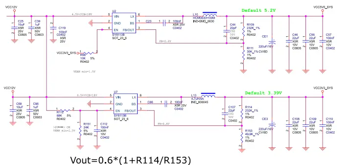
Litar Nyahpepijat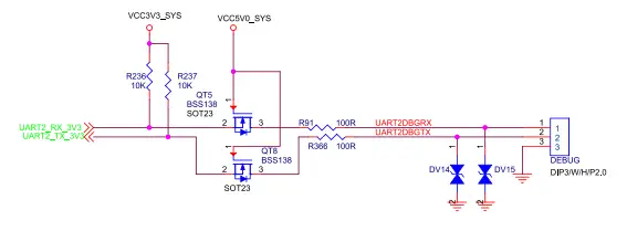
Litar Antaramuka OTG USB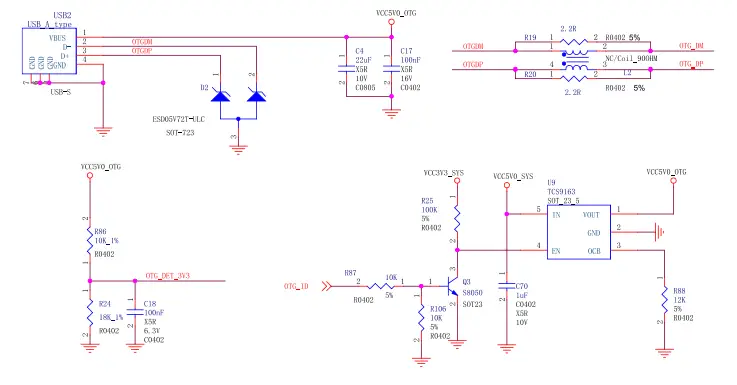
Jejak PCB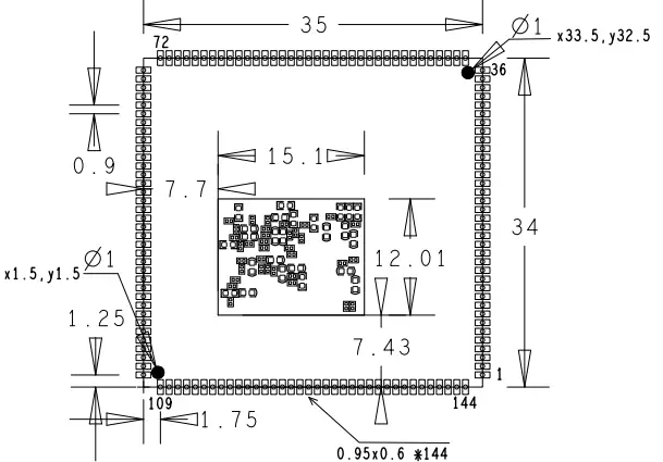
Ciri-ciri Elektrik Produk
Pelesapan dan Suhu
| Simbol | Parameter | Min | Taip | Maks | Unit |
| VCC3V3_SYS | Sistem IO
Voltage |
3.3-5% | 3.3 | 3.3 + 5% | V |
| Isys_in | VCC3V3_SYS input Semasa | 850 | mA | ||
| Ta | Suhu Operasi | -20 | 70 | °C | |
| Tstg | Suhu Penyimpanan | -40 | 85 | °C |
Kebolehpercayaan Ujian
| Ujian Pengendalian Suhu Tinggi | ||
| kandungan | Operating 8h in high temperatures | 55°C±2°C |
| Hasilnya | TBD |
| Ujian Kehidupan Operasi | ||
| kandungan | Operating in the room | 120j |
| Hasilnya | TBD |
Waranti Terhad
Boardcon warrants this product to be free of defects in material and workmanship for one year from the date of purchase. During this warranty period, Boardcon will repair or replace the defective unit by the following process: A copy of the original invoice must be included when returning the defective unit to Boardcon. This limited warranty does not cover damages resulting from lightning or other power surges, misuse, abuse, abnormal conditions of operation, or attempts to alter or modify the function of the product. This warranty is limited to the repair or replacement of the defective unit. In no event shall Boardcon be liable or responsible for any loss or damages, including but not limited to any lost profits, incidental or consequential damages, loss of business, or anticipatory profits arising from the use or inability to use this product. Repairs made after the expiration of the warranty period are subject to a repair charge and the cost of return shipping. Please contact Boardcon to arrange for any repair service and to obtain repair charge information.
Soalan Lazim
S: Bagaimanakah cara saya menaik taraf memori DDR pada CM1126B-P?
A: The CM1126B-P supports up to 4GB LPDDR4 memory. To upgrade, ensure compatibility with the specifications and follow recommended procedures.
S: Apakah keperluan bekalan kuasa untuk CM1126B-P?
A: The power requirement for CM1126B-P is DC 3.3V. Ensure to provide a stable power supply within this range for optimal performance.
S: Bolehkah saya mengembangkan kapasiti storan eMMC pada CM1126B-P?
A: Yes, the eMMC storage on CM1126B-P can be expanded up to 256GB. Ensure compatibility with supported storage devices before upgrading.
Dokumen / Sumber
 |
Sistem CM1126B-P Terbenam Boardcon pada Modul [pdf] Manual Pengguna V2.20250422, Sistem CM1126B-P pada Modul, CM1126B-P, Sistem pada Modul, Modul |