1. Pengenalan
This manual provides essential instructions for the installation, operation, and maintenance of your EPEVER 80A MPPT Solar Charge Controller. This device is designed to manage the power flow from your solar panels to your battery bank, ensuring efficient charging and protecting your batteries from overcharge and over-discharge. It supports 12V, 24V, 36V, and 48V battery systems automatically and is compatible with various lead-acid battery types including Sealed, AGM, Gel, and Flooded batteries.
2. Maklumat Keselamatan
Sila baca semua arahan dan amaran dengan teliti sebelum pemasangan dan pengendalian. Kegagalan mematuhi arahan ini boleh mengakibatkan renjatan elektrik, kebakaran atau kecederaan parah.
- Ensure all wiring is correctly polarized and securely connected. Incorrect wiring can damage the controller and other components.
- Always disconnect the battery first, then the solar panel, before performing any maintenance or disconnection. Reconnect in reverse order: solar panel first, then battery.
- Install the controller in a well-ventilated area, away from flammable materials and corrosive gases.
- The controller is designed for indoor use. Protect it from direct sunlight, high temperatures, and moisture.
- Use appropriate circuit breakers or fuses for both the solar panel and battery circuits to prevent overcurrent.
- This device is a common negative ground controller. Ensure proper grounding.
- Do not attempt to disassemble or repair the controller yourself. Contact qualified service personnel.
3. Produk Lebihview
3.1 Ciri-ciri Utama
- Sistem automatik voltage identification: 12V/24V/36V/48V DC.
- Advanced MPPT technology with ultra-fast tracking speed (up to 99.5% efficiency).
- Maximum DC/DC transfer efficiency up to 98.7%.
- Automatic control system to limit charging power and current.
- Real-time energy recording and statistical functions.
- Fungsi pampasan suhu bateri.
- Isolated RS-485 communication interface with MODBUS protocol.
- Support for parallel operation of up to 8 units to expand system capacity.
- Compatible with Sealed, AGM, Gel, and Flooded lead-acid batteries.
3.2 Dimensi Fizikal

Rajah 3.2.1: Physical dimensions of the EPEVER 80A MPPT Solar Charge Controller. The controller measures approximately 394mm (L) x 240mm (W) x 134mm (H).
The controller has a robust design with integrated heat sinks for efficient thermal management. The overall dimensions are approximately 394mm in length, 240mm in width, and 134mm in height. The mounting holes are designed for secure installation.
3.3 Pengenalan Komponen
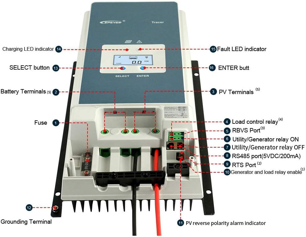
Rajah 3.3.1: Depan view of the EPEVER 80A MPPT Solar Charge Controller with labeled components.
- Fius: Overcurrent protection for the battery circuit.
- Terminal Bateri: Connect to the battery bank.
- PV Terminals: Connect to the solar panel array.
- Load Control Relay: Output for connecting DC loads (if applicable).
- RBVS Port: Bateri Jauh Voltage Sensor port.
- Utility/Generator Relay ON: Control signal for external utility/generator.
- Utility/Generator Relay OFF: Control signal for external utility/generator.
- RS485 Port (5VDC/200mA): Communication port for remote monitoring or parallel connection.
- RTS Port: Remote Temperature Sensor port.
- Generator and Load Relay Enable: Control input for generator and load relays.
- PV Reverse Polarity Alarm Indicator: LED indicator for PV reverse polarity.
- Terminal Pembumian: For system grounding.
- Butang PILIH: Used to navigate menu options.
- Penunjuk LED Pengecasan: Menunjukkan status pengecasan.
- Fault LED Indicator: Indicates system faults.
- Butang ENTER: Digunakan untuk mengesahkan pilihan.
3.4 Antara Muka Paparan

Rajah 3.4.1: Example screens of the LCD display showing various system parameters.
The integrated LCD provides real-time monitoring of system parameters such as PV voltage, arus pengecasan, vol bateritage, load status, and temperature. Use the "SELECT" and "ENTER" buttons to navigate through the display screens and adjust settings.
4. Persediaan & Pemasangan
Proper installation is crucial for the safe and efficient operation of your solar charge controller. Follow these steps carefully.
4.1 Memasang Pengawal
- Choose a vertical mounting location that is well-ventilated and protected from direct sunlight, high temperatures, and moisture.
- Ensure there is sufficient clearance around the controller for heat dissipation, especially above and below the heat sink fins.
- Mount the controller securely using appropriate fasteners for the mounting surface.
4.2 Sambungan Pendawaian
Penting: Always connect the battery first, then the solar panel. Disconnect in the reverse order: solar panel first, then battery. Ensure all connections are tight and secure to prevent loose connections and overheating.

Rajah 4.2.1: Standard connection diagram for the EPEVER 80A MPPT Solar Charge Controller with a single battery, PV panel, and AC load via an inverter.
- Sambungkan Bateri: Connect the positive and negative terminals of the battery bank to the controller's battery terminals. Observe correct polarity. Use recommended cable size (e.g., 16mm² / 6AWG).
- Sambungkan Panel Suria: Connect the positive and negative terminals of the solar panel array to the controller's PV terminals. Ensure the PV open circuit voltage tidak melebihi 150VDC.
- Sambungkan Beban (Pilihan): If using the load control feature, connect your DC load to the controller's load terminals.
- Connect Remote Temperature Sensor (RTS): Plug the RTS cable into the RTS port. This ensures accurate battery temperature compensation.
- Connect Remote Battery Voltage Sensor (RBVS) (Optional): Plug the RBVS cable into the RBVS port for more accurate battery voltage pengukuran.
- Pembumian: Connect the grounding terminal of the controller to an earth ground.
4.3 Sambungan Selari (Pilihan)
The EPEVER 80A MPPT controller supports parallel operation of up to 8 units to increase system capacity. This requires an RS485 communication cable and proper configuration.
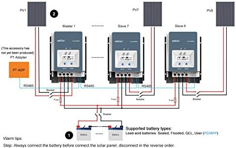
Rajah 4.3.1: Diagram illustrating the parallel connection of multiple EPEVER MPPT controllers to a single battery bank.
For parallel connection, ensure all controllers are connected to the same battery bank and configured correctly via the RS485 communication port. Refer to the advanced user manual for detailed instructions on parallel setup and master/slave configuration.
4.4 Pemilihan Jenis Bateri
The controller supports various lead-acid battery types. It is crucial to select the correct battery type in the controller's settings to ensure optimal charging and battery longevity.
- Dimeteraikan: For sealed lead-acid batteries.
- AGM: Untuk bateri Tikar Kaca Serap.
- Gel: For Gel cell batteries.
- banjir: For flooded (wet cell) lead-acid batteries.
- pengguna: Allows for custom charging parameters for specific battery types (e.g., non-standard lead-acid or user-defined settings). Note: This controller is not designed for Lithium batteries.
Refer to your battery manufacturer's specifications for recommended charging voltages and select the corresponding type in the controller's menu. Incorrect battery type selection can damage your batteries.
5. Operasi
5.1 Kuasa Permulaan
After all connections are made and verified, the controller will power on automatically. The LCD display will show the current system status. The Charging LED indicator will illuminate when charging is active.
5.2 Status Sistem Pemantauan
Use the "SELECT" button to cycle through various display screens, showing parameters such as:
- PV Voltage (V) and Current (A)
- Bateri Voltage (V) and Charging Current (A)
- Beban Voltage (V) and Current (A)
- Battery Temperature (°C)
- Total Charged Energy (kWh)
- Total Discharged Energy (kWh)
5.3 Tetapan Parameter
To enter the parameter setting mode, press and hold the "ENTER" button for a few seconds. Use the "SELECT" button to navigate through parameters and the "ENTER" button to confirm changes. Parameters that can be adjusted include:
- Jenis Bateri
- Mengecas Voltage Setpoints (Float, Boost, Equalization)
- Load Control Mode (e.g., always on, dusk to dawn, timer)
- Masa lampu latar LCD
- Pekali pampasan suhu
Refer to the detailed programming guide for specific values and advanced settings.
6. Penyelenggaraan
Regular maintenance ensures the longevity and optimal performance of your charge controller.
- Semak Sambungan: Periodically inspect all wiring connections for tightness, corrosion, or damage. Tighten any loose connections.
- Bersihkan Pengawal: Keep the controller clean and free of dust and debris. Use a dry cloth to wipe the exterior. Ensure the heat sink fins are not obstructed.
- Periksa Kerosakan: Check for any physical damage to the casing, cables, or terminals.
- Pantau Prestasi: Regularly check the display for normal operation and compare readings with expected values.
- Penyelenggaraan Bateri: Follow your battery manufacturer's maintenance guidelines.
7. Penyelesaian masalah
Bahagian ini menggariskan isu-isu biasa dan potensi penyelesaiannya. Jika masalah berterusan, hubungi khidmat pelanggan.
7.1 Common Protections and Indicators
The controller includes several protection mechanisms. The Fault LED indicator will illuminate or flash to indicate a fault condition.
- PV Over Current/Power: The solar input power or current exceeds the controller's rated limits. The controller will automatically limit the charging. Check PV array size.
- PV Short Circuit: A short circuit in the solar panel wiring. Disconnect PV, check wiring, and reconnect.
- PV Reverse Polarity: Solar panel connected with incorrect polarity. Disconnect PV, correct wiring, and reconnect. The PV reverse polarity alarm indicator will be active.
- Night Reverse Charging: Current flowing from battery to PV at night. This is usually prevented by the controller; if it occurs, check PV wiring.
- Bateri Lebih Voltage: Bateri voltage exceeds the overcharge protection setting. The controller will stop charging.
- Battery Over Discharge: Bateri voltage drops below the over-discharge protection setting. The load output will be disconnected.
- Bateri Terlalu Panas: Battery temperature is too high. Charging current will be reduced or stopped. Ensure proper battery ventilation.
- Controller Overheating: Internal temperature of the controller is too high. Charging current will be reduced. Ensure adequate ventilation around the controller.
- TVS High Voltage Transients: Internal protection against voltage lonjakan.
7.2 Langkah Penyelesaian Masalah Umum
- Tiada Paparan/Tiada Kuasa: Check battery connections and fuse. Ensure battery voltage is within the operating range (8V~68V).
- Tiada Pengecasan: Check PV connections, ensure solar panels are receiving sunlight, and verify PV voltage is sufficient (above battery voltage). Check for PV short circuit or reverse polarity.
- Arus Pengecasan Rendah: Check PV array size, shading, and battery state of charge. Ensure battery type settings are correct.
- Beban Tidak Berfungsi: Check load connections, ensure battery voltage is above over-discharge protection, and verify load control settings.
8. Spesifikasi
| Parameter | Nilai |
|---|---|
| Sistem Voltage | 12V / 24V / 36V / 48V DC Auto |
| Kadar Caj Semasa | 80A |
| Maks. Kuasa Input PV | 1000W (12V), 2000W (24V), 3000W (36V), 4000W (48V) |
| Maks. Litar Terbuka PV Voltage | 150VDC |
| Pemilihan Jenis Bateri | Lead-acid (Gel, Sealed, AGM, Flooded) and User |
| Pembumian | Common Negative Ground |
| Bateri Input Voltage Julat | 8V ~ 68V |
| Pampasan Suhu | -3mV / ℃ / 2V (Lalai) |
| Saiz Kabel yang Disyorkan | 16mm² (6AWG) |
| Dimensi (L x W x H) | 394mm × 236mm × 119mm |
| Berat badan | 4.5kg (9.92 paun) |
| Komunikasi | Isolated RS-485 (5VDC/200mA) with MODBUS protocol |
| Maks. Kecekapan | 98.7% |
9. Waranti & Sokongan
EPEVER products are designed for reliability and performance. This product comes with a standard manufacturer's warranty against defects in materials and workmanship. Please refer to the warranty card included with your product or visit the official EPEVER webtapak untuk terma dan syarat jaminan terperinci.
For technical support, troubleshooting assistance, or warranty claims, please contact EPEVER customer service through their official website or the contact information provided in your product packaging. When contacting support, please have your product model number and purchase date available.
Webtapak: www.epever.com (Example link, actual link may vary)