1. Pengenalan
This manual provides comprehensive instructions for the installation, operation, and maintenance of the Generic NY-D01 40A Spot Welder Control Board. This control board is designed to enhance precision and safety in resistance spot welding applications. It features a digital interface for displaying time and current settings, an optocoupler for strong and weak current isolation, and a zero-crossing detection circuit for accurate thyristor phase shifting. Please read this manual thoroughly before use to ensure proper functionality and safety.
2. Maklumat Keselamatan
Sentiasa patuhi langkah berjaga-jaga keselamatan berikut untuk mengelakkan kecederaan atau kerosakan pada peralatan:
- Bahaya Elektrik: This device operates with electrical currents. Ensure all power is disconnected before installation, maintenance, or troubleshooting.
- Pemasangan Profesional: Installation should be performed by qualified personnel familiar with electrical circuits and welding equipment.
- Pembumian yang betul: Ensure all connected equipment, including the spot welder, is properly grounded.
- Pengudaraan: Operate in a well-ventilated area to prevent overheating of components.
- Pengendalian Komponen: Handle the control board with care to avoid damage to sensitive electronic components. Avoid static discharge.
- Pengasingan: The board incorporates optocouplers for strong and weak current isolation. Do not bypass or modify these safety features.
- Keserasian: Ensure the control board's specifications (e.g., 40A current rating) are compatible with your existing spot welding setup and SCR.
3. Produk Lebihview
The NY-D01 40A Spot Welder Control Board is designed for precise control of resistance spot welding machines. Key features include:
- Antara Muka Digital: Displays current time and settings for precise control.
- Zero-Crossing Detection: Ensures accurate thyristor phase shifting for consistent welds.
- Optocoupler Isolation: Separates strong and weak currents for enhanced safety.
- Quick Connection Terminals: Screwless terminals for easy and reliable power and foot switch connections.
- User-Friendly Input: High-precision single potentiometers for adjusting time and current settings.
- Industrial Microcontroller: Managed by an STM8 industrial microcontroller for stable performance.
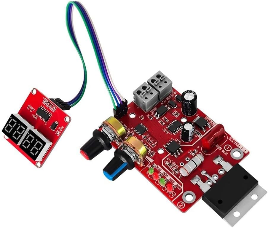
Rajah 3.1: Secara keseluruhan view of the NY-D01 40A Spot Welder Control Board. This image shows the main circuit board with its various components, including the potentiometers for adjustment, the digital display interface, and the quick connection terminals.

Figure 3.2: The main control board alongside its separate digital display module. This view highlights the connection cable between the two components and the potentiometers for time and current adjustment.

Figure 3.3: The control board with a clear "40A" marking, indicating its current rating. This confirms the specific variant of the product.
4. Persediaan dan Pemasangan
Before proceeding with installation, ensure all power to the spot welder and associated equipment is disconnected. Refer to the wiring diagram provided with your specific spot welder for detailed connection points.
4.1 Pengenalan Komponen
Familiarize yourself with the main components of the control board:
- Main Control Board: Contains the microcontroller, power regulation, and connection terminals.
- Digital Display Module: Connects to the main board to show time and current settings.
- Potensiometer: Two rotary knobs for adjusting welding time and current.
- Quick Connection Terminals: For power input (AC9-12V) and foot switch connection.
- SCR Connection Points: Terminals for connecting to the 100A SCR (Thyristor).
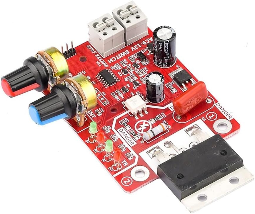
Rajah 4.1: Jarak dekat view of the control board, highlighting the screwless quick connection terminals for power input (AC9-12V) and the foot switch. This image also shows the potentiometers and various indicator LEDs.
4.2 Arahan Pendawaian
- Connect Digital Display: Connect the digital display module to the main control board using the provided ribbon cable. Ensure correct orientation.
- Input Kuasa: Connect a 9-12V AC power source to the "AC9-12V" quick connection terminals on the main board. Ensure the power source is appropriate for the board's requirements.
- Foot Switch Connection: Connect your foot switch to the designated quick connection terminals. This switch acts as the trigger for the welding process.
- SCR Connection: Connect the control board to your 100A SCR (Thyristor) according to the SCR's documentation. The board provides control signals for the SCR's gate.
- Main Welding Circuit: Ensure your main welding circuit, including the transformer and electrodes, is correctly wired and safely isolated from the control circuit.
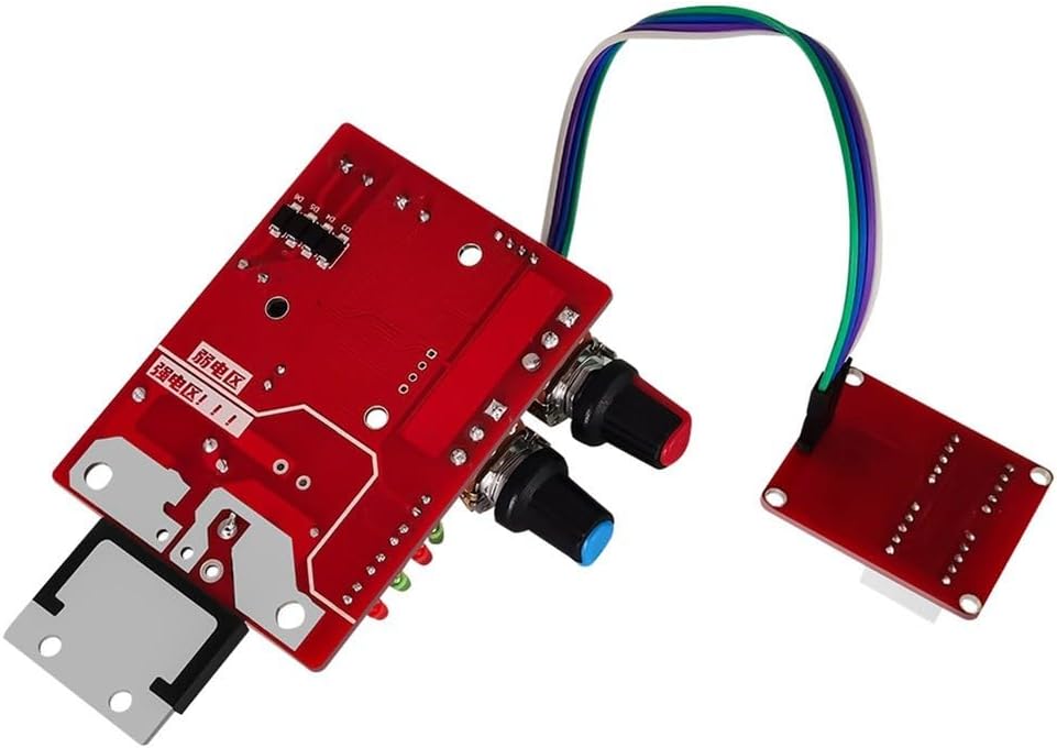
Rajah 4.2: Belakang view or alternative angle of the control board, showing the layout of components and potential mounting points. This view can assist in understanding the physical integration into a welding setup.
5. Arahan Operasi
Once the control board is correctly installed and powered, follow these steps for operation:
5.1 Hidupkan
Apply power to the control board. The digital display should illuminate, and the power indicator LED (PWR) on the main board should light up.
5.2 Melaraskan Parameter Kimpalan
Use the two potentiometers to set the desired welding time and current:
- Time Potentiometer: Adjusts the welding duration. The unit is typically in cycles (1 cycle = 20 milliseconds for 50Hz AC). The range is 1-50 cycles.
- Current Potentiometer: Adjusts the welding current intensity. This controls the phase angle of the SCR, thereby regulating the power delivered to the welding transformer.
The digital display will show the adjusted values in real-time. Experiment with settings on scrap material to find optimal parameters for your specific welding task and material thickness.
5.3 Initiating a Weld
With the welding parameters set, position your workpieces between the spot welder electrodes. Press the foot switch to initiate the welding cycle. The foot trigger indicator LED (TR) should light up during the weld.
The STM8 industrial microcontroller manages the precise timing and current delivery based on your settings and the zero-crossing detection circuit.
6. Penyelenggaraan
Regular maintenance ensures the longevity and reliable operation of your NY-D01 40A Spot Welder Control Board:
- Pembersihan: Keep the board free from dust, metal particles, and moisture. Use a soft, dry brush or compressed air for cleaning. Ensure power is disconnected before cleaning.
- Pemeriksaan Sambungan: Periodically inspect all quick connections and wiring for looseness or damage. Ensure secure connections to prevent intermittent operation or electrical hazards.
- Keadaan Persekitaran: Operate and store the board in a dry, clean environment within its specified temperature range. Avoid extreme temperatures and humidity.
- Pemeriksaan Komponen: Visually inspect components for any signs of damage, such as burnt resistors or bulging capacitors. If damage is observed, discontinue use and consult a qualified technician.
7. Penyelesaian masalah
If you encounter issues with your control board, refer to the following common problems and solutions:
| Masalah | Kemungkinan Punca | Penyelesaian |
|---|---|---|
| No Power/Display Off | Tiada bekalan kuasa, volum salahtage, sambungan longgar. | Check power input (AC9-12V) and ensure connections are secure. Verify power supply is functional and provides correct voltage. |
| Welder Not Firing | Foot switch not connected, faulty foot switch, SCR not connected or faulty, incorrect settings. | Verify foot switch connection and functionality. Check SCR wiring and ensure it is operational. Adjust time and current settings. |
| Inconsistent Welds | Incorrect time/current settings, poor electrode contact, issues with main welding circuit. | Adjust time and current potentiometers. Ensure electrodes are clean and making good contact. Inspect main welding transformer and wiring. |
| Digital Display Malfunction | Loose ribbon cable, faulty display module. | Check the connection of the ribbon cable between the main board and the display module. |
If the problem persists after attempting these solutions, contact customer support or a qualified technician.
8. Spesifikasi
| Ciri | Perincian |
|---|---|
| Nombor Model | NY-D01 40A (Item model number: 2E8F5PH63C2H4R3J5IP6R0I14S8) |
| Keserasian | Designed for 100A SCR (Thyristor) |
| Input Voltage | AC 9-12V (for control board power) |
| Penilaian Semasa | 40A (Control Board) |
| Time Input Range | 1-50 cycles (1 cycle = 20 milliseconds) |
| Kaedah Kawalan | Digital interface with potentiometers, STM8 industrial microcontroller |
| Ciri Keselamatan | Optocoupler isolation, Zero-Crossing Detection |
| Jenis Sambungan | Screwless quick connection terminals |
| Dimensi Produk | 5.12 x 3.15 x 0.79 inci (13 x 8 x 2 cm) |
| Berat Barang | 2.29 auns (65 gram) |
| Pengeluar | Generik |

Figure 8.1: Dimensions of the NY-D01 Spot Welder Control Board. The image indicates approximate measurements of 10.4cm (4.09 inches) in length, 8cm (3.14 inches) in width, and 6cm (2.36 inches) for the heat sink component.
9. Waranti dan Sokongan
This product is covered by a standard manufacturer's warranty against defects in materials and workmanship. For specific warranty terms and duration, please refer to the documentation provided at the time of purchase or contact your retailer.
For technical support, troubleshooting assistance, or inquiries regarding replacement parts, please contact the retailer or manufacturer directly. When contacting support, please have your product model number (NY-D01 40A) and any relevant purchase information available.


