1. Produk Lebihview
The NEWFAST B912 Outdoor WiFi Bridge is designed to extend your network coverage over long distances, up to 3 kilometers (1.9 miles). It operates on the 5.8GHz band with a speed of 300Mbps, making it ideal for connecting remote buildings, farms, garages, warehouses, or security cameras. Equipped with an 11dBi directional antenna, passive PoE, and an IP66-rated weatherproof enclosure, it ensures stable and reliable outdoor performance.
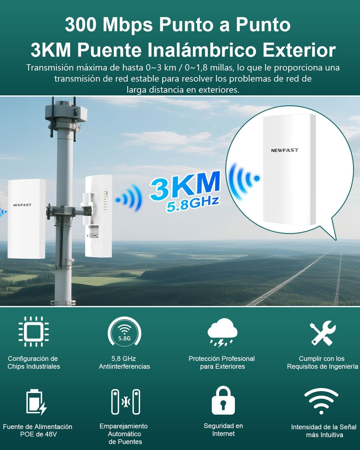
Imej 1: Selesaiview of the NEWFAST B912 WiFi Bridge highlighting its 3KM range and 300Mbps speed.
Ciri-ciri Utama:
- Liputan Lanjutan: Expands network up to 3 kilometers (1.9 miles).
- Point-to-Point Connection: Connects two locations for high-speed WiFi.
- Berbilang Mod Pengendalian: Supports point-to-point and point-to-multipoint configurations.
- Reka Bentuk Kalis Cuaca: IP66 rated for outdoor use, resistant to dust, water, and extreme temperatures.
- PoE Passive Power: Simplifies installation with power and data over a single Ethernet cable.
- 11dBi Directional Antenna: Ensures strong and stable signal transmission.
- Keselamatan Rangkaian: Features like SSID hiding for enhanced protection.
2. Apa yang Termasuk
Pakej mengandungi item berikut:
- 1 pair WiFi Bridge (2 units)
Video 1: Unboxing and package contents for the CPE Wireless Bridge Kit.
Text Description: This video shows the unboxing of a similar CPE kit, demonstrating the two CPE units, PoE adapters, Ethernet cables, and mounting accessories typically included.
3. Arahan Persediaan
3.1 Powering the CPE Units
The CPE units can be powered in two ways: via a PoE injector or directly via a DC power adapter. The PoE injector allows both power and data to be transmitted over a single Ethernet cable.
- Via PoE Injector: Connect the PoE/LAN port of the CPE to the PoE port of the injector using an Ethernet cable. Connect the DC power adapter to the injector and plug it into an electrical outlet.
- Via DC Power Adapter: Alternatively, connect the DC power adapter directly to the CPE's DC port.
Video 2: Demonstrates powering the CPE units using a PoE injector and direct DC adapter. (Relevant segment: 0:13 - 0:41)
3.2 Penggandingan Automatik
Automatic pairing is applicable when the CPEs are in their factory default configuration. The pairing process typically takes less than 1 minute after both CPEs are powered on in the same room.
- Place both CPE units in the same room and power them on.
- One unit will automatically configure as an Access Point (AP/Transmitter) and the other as a Station (Receiver). You can identify each unit by checking the labels on their rear side.
- Once both CPEs are powered on, the PoE/LAN indicator on each CPE will light up solid green.
- When the LED1 and LED2 indicators on the AP (Transmitter) light up solid, and the LED1 and LED2 indicators on the Station (Receiver) blink slowly, automatic pairing is successful.
Video 3: Illustrates the automatic pairing process and LED indicators for successful connection. (Relevant segment: 0:42 - 1:30)
3.3 Installation and Placement
For optimal performance, proper placement and alignment are crucial. Ensure a clear line of sight between the two CPE units.
- Mount the CPE units outdoors in suitable locations.
- When choosing locations, ensure the AP (Transmitter) and Station (Receiver) have a clear line of sight between them. Obstructions like trees or buildings can significantly degrade signal quality.
- Point the front of the AP (Transmitter) towards the front of the Station (Receiver). For optimal signal transmission, they should be 100% face-to-face.
- In certain circumstances, you may need to align the station vertically or horizontally to point directly at the front of the access point within a 60-degree angle range.

Image 2: Diagram illustrating wall and pole mounting options for easy installation.
Video 4: Demonstrates the importance of clear line of sight and proper alignment between CPE units. (Relevant segment: 1:31 - 2:09)
3.4 Sambungan Titik-ke-Titik
This is the most common setup, extending your network from one building to another.
- Connect the AP (Transmitter) to your upstream network device, such as your main modem/router or an Ethernet switch, using an Ethernet cable.
- Connect the Station (Receiver) to an Ethernet device, such as another WiFi router, an Ethernet switch, or an IP camera, using an Ethernet cable.

Image 3: Diagram illustrating a typical point-to-point connection setup, extending network from a main house to another building.
Video 5: Shows the final setup for a point-to-point connection. (Relevant segment: 2:10 - 2:30)
3.5 Point-to-Multipoint Connection
For PtMP applications, you must manually configure the AP (Transmitter) and Station (Receiver) through the user interface pages. This requires a good understanding of network configuration. Up to 15 Station (Receiver) units can be bridged to 1 AP (Transmitter).

Image 4: Diagram illustrating a point-to-multipoint connection, where one Master CPE connects to multiple Slave CPEs for monitoring.
Video 6: Explains the point-to-multipoint topology and the need for manual configuration. (Relevant segment: 3:20 - 3:35)
4. Mengendalikan Peranti
4.1 Checking Signal Strength
You can check the signal intensity through the LED1 and LED2 signal indicators on the CPE units. The LED indicators light up when the received signal intensity reaches the threshold of the corresponding LED indicator.
- Good Signal: Both LED1 and LED2 indicators on the AP (Transmitter) remain solid green, while the LED1 and LED2 indicators on the Station (Receiver) blink slowly.
- Decent Signal: The LED1 indicator on the AP (Transmitter) remains solid green, while the LED2 indicator turns off. On the Station (Receiver), the LED1 indicator blinks slowly, and the LED2 indicator turns off.
- Regular or No Signal: Both LED1 and LED2 indicators on the AP (Transmitter) turn off, and the corresponding LED1 and LED2 indicators on the Station (Receiver) also turn off.
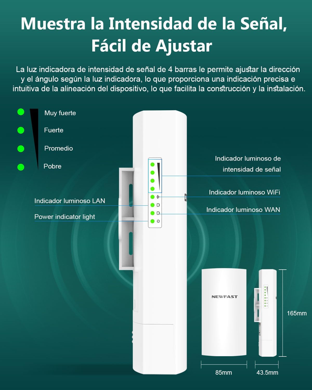
Image 5: Visual guide to the signal strength LED indicators on the CPE unit.
Video 7: Explains how to interpret the LED indicators for signal strength. (Relevant segment: 2:31 - 3:13)
5. Penyelenggaraan
The NEWFAST B912 is designed for outdoor use with an IP66 rating, providing protection against dust and water. Regular maintenance is minimal, but consider the following:
- Pemeriksaan Berkala: Periodically check the physical mounting and cable connections for any signs of wear or damage.
- Garis Penglihatan yang Jelas: Ensure that no new obstructions (e.g., growing trees or new structures) block the line of sight between the units.
- Pembersihan: Jika perlu, bersihkan bahagian luar unit dengan lembutamp cloth to remove dirt or debris. Avoid harsh chemicals.
6. Penyelesaian masalah
Isu dan Penyelesaian Biasa:
- No Signal / Poor Signal:
- Check LED indicators as described in Section 4.1.
- Verify clear line of sight between units. Remove any obstructions.
- Ensure proper alignment of the units. Adjust their angle for optimal signal.
- Periksa semua sambungan kabel untuk memastikan ia dipasang dengan selamat.
- Units Not Powering On:
- Ensure power adapters are correctly connected and plugged into working outlets.
- If using PoE, verify the Ethernet cable is connected to the correct PoE port on both the CPE and the injector.
- Automatic Pairing Fails:
- Ensure both units are in factory default settings. If not, perform a factory reset (refer to the full configuration manual for details).
- Place units in the same room during initial pairing.
- Slow Wired Transmission Speed (Limited to 100 Mbps):
- Note that the wired transmission speeds are limited to 100 Mbps by the RJ45 Ethernet port. This is a product specification, not a fault.
7. Spesifikasi
| Ciri | Spesifikasi |
|---|---|
| Jenama | PUASA BARU |
| Nama Model | B912 |
| Jenis Sambungan Wayarles | 802.11a, 802.11n |
| Kelas Band Kekerapan | Jalur Tunggal (5.8GHz) |
| Kadar Pemindahan Data | 300Mbps |
| Antena | Antena Berarah 11dBi |
| Bekalan Kuasa | Passive PoE (48V) |
| Penilaian Perlindungan | IP66 |
| warna | putih |
| Dimensi | 29 x 23 x 5 cm |
| Berat badan | 850 g |
| Ciri Khas | Penunjuk LED |
8. Waranti dan Sokongan
For warranty information and technical support, please refer to the documentation included with your product or visit the official NEWFAST webtapak. Simpan resit pembelian anda untuk tuntutan waranti.