
1. Pengenalan
This manual provides instructions for the assembly, setup, operation, and maintenance of the Weytoll Signal Generator Kit. This device is a DIY (Do-It-Yourself) kit designed to generate various waveforms including sine, square, triangular, and sawtooth waves, with an adjustable frequency range from 1Hz to 20MHz.
As this is a DIY kit, user assembly is required. Please read all instructions carefully before beginning assembly or operation.
2. Maklumat Keselamatan
Sentiasa patuhi langkah keselamatan berikut:
- Pastikan bekalan kuasa voltage berada dalam julat yang ditentukan (9V hingga 15V DC).
- Jangan kendalikan peranti dalam keadaan basah atau damp syarat.
- Avoid touching exposed circuit components when the device is powered on.
- Use appropriate tools and follow proper soldering techniques during assembly to prevent damage to components or injury.
- Jauhkan peranti daripada kanak-kanak.
3. Kandungan Pakej
Verify that all components listed below are present in your kit. If any parts are missing or damaged, please contact customer support.
- 1x Signal Generator PCB (Printed Circuit Board)
- 1x Acrylic Casing Set (Top and Bottom panels, screws)
- Electronic Components (Resistors, Capacitors, ICs, Potentiometers, Connectors, etc.)
- 1x Manual Pengguna (dokumen ini)
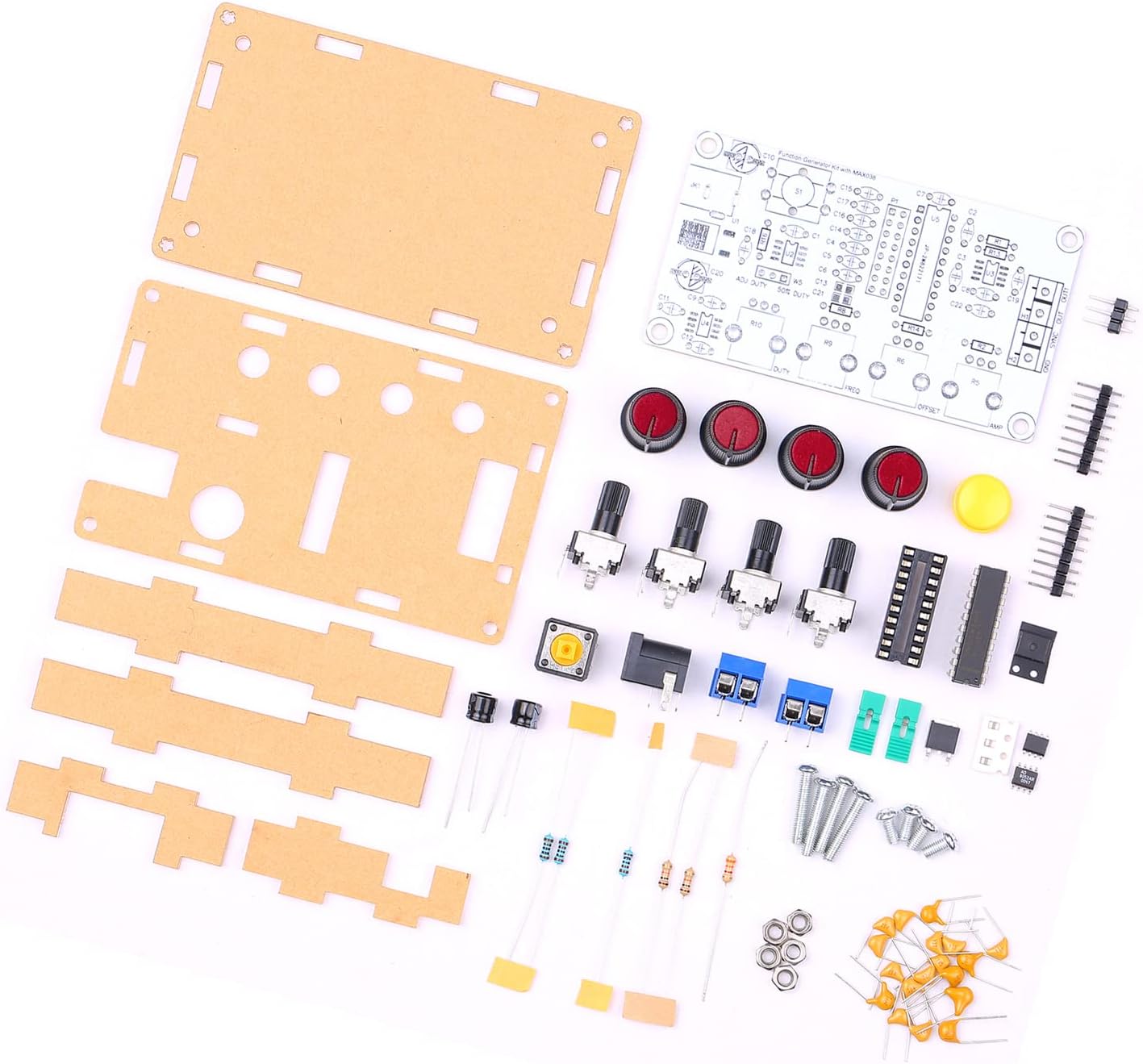
Figure 3.1: All components included in the Weytoll Signal Generator Kit.
4. Arahan Perhimpunan
Assembly of this kit requires basic soldering skills and tools (soldering iron, solder, wire cutters, multimeter recommended). Follow the steps below carefully.
- Pengenalan Komponen: Before soldering, identify all components using the provided circuit diagram (if included, otherwise refer to component markings). Sort resistors by value, capacitors by type and value, and identify integrated circuits (ICs).
- Solder Smaller Components First: Begin by soldering the smallest components to the PCB, such as resistors and diodes, followed by capacitors, IC sockets (if using), and then the ICs themselves. Pay attention to polarity for diodes, electrolytic capacitors, and ICs.
- Install Larger Components: Solder the larger components like potentiometers, connectors (power jack, output terminals), and switches. Ensure they are flush with the PCB and correctly oriented.
- Verify Soldering: After all components are soldered, carefully inspect all solder joints for bridges, cold joints, or missing connections. Use a multimeter to check for continuity where appropriate.
- Assemble Acrylic Casing:
- Remove protective film from both sides of the acrylic panels.
- Attach the bottom acrylic panel to the PCB using the provided standoffs and screws.
- Align the top acrylic panel, ensuring all potentiometers, switches, and connectors fit through their respective openings. Secure with the remaining screws.
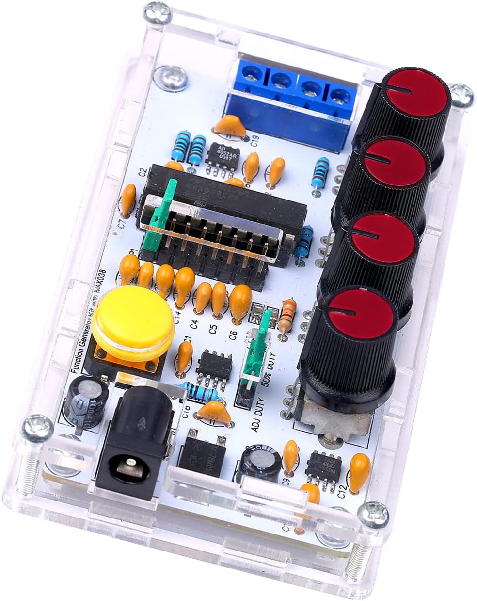
Figure 4.1: Fully assembled signal generator kit.
5. Persediaan
Once assembled, follow these steps to set up your signal generator:
- Sambungan Kuasa: Connect a DC power supply (9V to 15V) to the power input jack. Ensure correct polarity.
- Sambungan Output: Connect the signal output (OUT) to your desired measurement device (e.g., oscilloscope, frequency counter) using appropriate cables. The SYNC OUT provides a synchronization signal.
- Tetapan Awal: Before powering on, set all potentiometer knobs to their center positions or minimum values to avoid unexpected outputs.
6. Arahan Operasi
The Weytoll Signal Generator Kit allows for adjustment of frequency, duty cycle, DC offset, and amplitude. It can generate sine, square, triangular, and sawtooth waveforms.
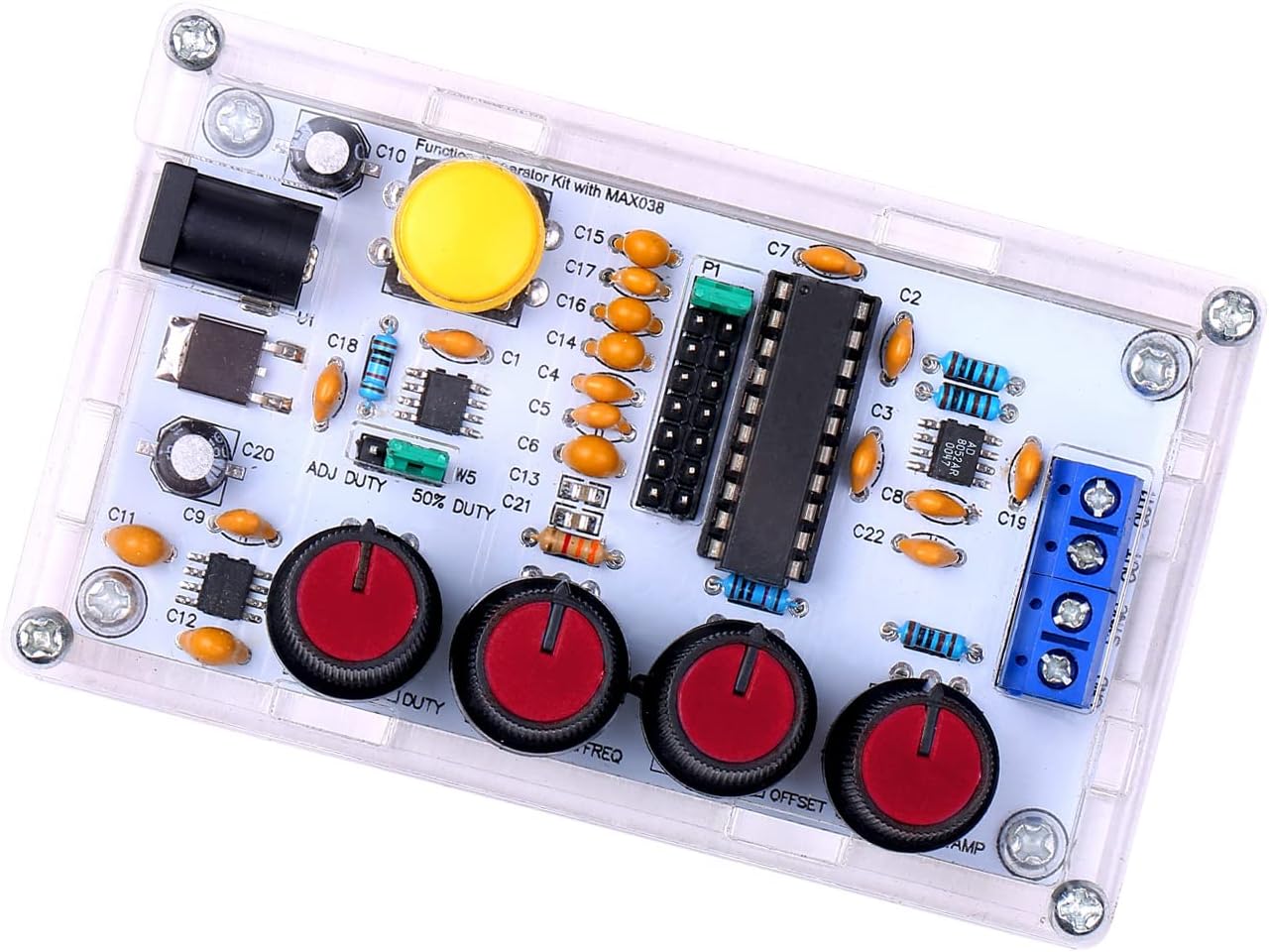
Figure 6.1: Control knobs for signal adjustment.
- Frequency Adjustment (FREQ): Use the FREQ knob to adjust the output frequency from 1Hz to 20MHz.
- Duty Cycle Adjustment (DUTY): Use the DUTY knob to adjust the duty cycle of square and sawtooth waves from 15% to 85%.
- DC Offset Adjustment (OFFSET): The OFFSET knob allows for adjusting the DC offset of the output signal from -5V to +5V.
- Amplitude Adjustment (AMP): Gunakan AMP knob to adjust the peak-to-peak amplitude of the output signal from 0.1VPP to 9.5VPP (with a 9V operating voltagdan).
- Pemilihan Bentuk Gelombang: The kit supports output of triangular, square, sine, and forward/reverse sawtooth waves. Refer to the PCB markings or a detailed circuit diagram for specific waveform selection points or switches, if present.
- Synchronization Output (SYNC OUT): This terminal provides a synchronization signal, useful for triggering oscilloscopes or other external devices.
7. Penyelenggaraan
The Weytoll Signal Generator Kit requires minimal maintenance:
- Pembersihan: Pastikan peranti bersih dan bebas daripada habuk. Gunakan kain lembut dan kering untuk pembersihan. Jangan gunakan pembersih cecair.
- Storan: Store the device in a dry, cool environment when not in use.
- Pemeriksaan: Periodically inspect the connections and solder joints for any signs of wear or damage.
8. Penyelesaian masalah
If you encounter issues with your signal generator, refer to the following troubleshooting guide:
| Masalah | Kemungkinan Punca | Penyelesaian |
|---|---|---|
| Tiada isyarat keluaran |
|
|
| Incorrect frequency/waveform |
|
|
| Bentuk gelombang terherot |
|
|
Jika masalah berterusan selepas mencuba penyelesaian ini, sila hubungi sokongan pelanggan.
9. Spesifikasi
The following are the technical specifications for the Weytoll Signal Generator Kit:
| Parameter | Nilai |
|---|---|
| Nombor Model | XXI0262789081113FJ |
| bahan | PCB + Acrylic |
| Frequency Adjustment Range | 1Hz ~ 20MHz |
| Duty Cycle Adjustment Range | 15% ~ 85% |
| Low Loss True Sine Wave | 0.75% |
| Triangular Wave Output Linearity | 0.1% |
| Low Impedance Output Buffer | 0.1Ω |
| Adjustable DC Offset | -5V ~ 5V |
| Output Boleh Laras Amplilitan | 0.1VPP ~ 9.5VPP (with 9V operating voltage) |
| Operasi Bekalan Kuasa Voltage | 9V ~ 15V DC |
| Hanyut Suhu | 200 ppm/°C |
| Dimensi Item (L x W x H) | 99 x 59 x 32 mm (3.90 x 2.32 x 1.26 inci) |
| Berat Barang | 82 g |
| Dimensi Pakej | 17.78 x 15.24 x 1.78 cm (7 x 6 x 0.7 inci) |
| Berat Pakej | 89 g |

Figure 9.1: Physical dimensions of the signal generator.
10. Waranti dan Sokongan
Warranty information for the Weytoll Signal Generator Kit is not explicitly provided in the product details. Please refer to your purchase documentation or contact the seller directly for warranty terms and conditions.
For technical support or inquiries regarding assembly and operation, please contact Weytoll customer service through the retailer's platform or their official website, if available.