
1. Pengenalan
The DAOKAI NE555 Pulse Generator Module is a compact, single-channel signal output device designed for generating adjustable frequency square waves. Utilizing the versatile NE555 timer integrated circuit, this module is suitable for various applications including microcontroller unit (MCU) learning, electronic competitions, and product development. It provides a stable square wave output with an approximate 50% duty cycle, and its frequency can be easily adjusted via an onboard potentiometer.
This manual provides detailed instructions for the setup, operation, and maintenance of your NE555 Pulse Generator Module.

Imej 1.1: Selesaiview of the DAOKAI NE555 Pulse Generator Modules and included Dupont cable.
2. Kandungan Pakej
Selepas membuka pakej, sahkan bahawa semua komponen ada dan tidak rosak:
- 5 x NE555 Pulse Generator Modules
- 1 x 15-pin Female to Male Dupont Cable
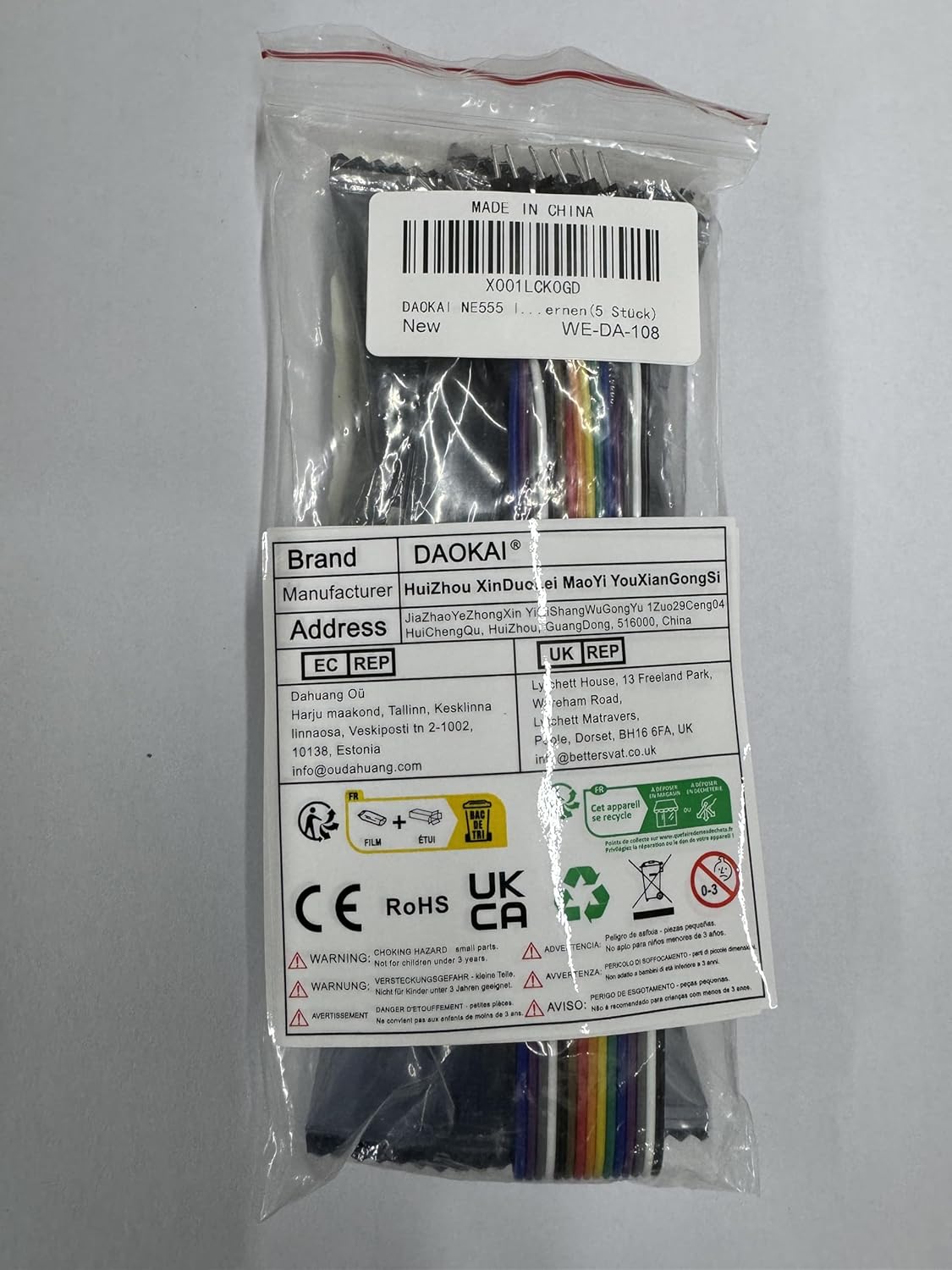
Image 2.1: Packaging of the NE555 Pulse Generator Modules and Dupont cable. The label indicates model WE-DA-108.
3. Spesifikasi
Refer to the following technical specifications for the NE555 Pulse Generator Module:
- Cip: Onboard NE555 timer IC
- Bekerja Voltage: 5V hingga 12V DC
- Isyarat Output: Single-channel square wave
- Output Duty Cycle: Kira-kira 50%
- Julat Kekerapan Keluaran: 5Hz to 2KHz (adjustable via potentiometer; can be modified by changing capacitor C1)
- Arus Keluaran: 225 mA (maksimum)
- Keluaran Voltage: Sama dengan input voltage
- Masa Kebangkitan/Kejatuhan: 100 ns
- Dimensi (L x W x H): 25mm x 13mm x 12mm (0.98in x 0.51in x 0.47in)

Image 3.1: Key parameters of the NE555 Pulse Generator Module.

Image 3.2: Physical dimensions of the NE555 Pulse Generator Module.
4. Persediaan dan Sambungan
The module features a simple 3-pin header for power and signal output. Follow these steps for proper connection:
- Kenal pasti Pin: The module has three pins labeled GND, OUT, and VCC.
- Sambungkan Kuasa:
- Sambungkan VCC pin to your DC power supply's positive (+) terminal (5V to 12V).
- Sambungkan GND pin to your DC power supply's negative (-) terminal (ground).
- Output Sambung: Sambungkan KELUAR pin to the input of the device or circuit you wish to drive with the pulse signal.

Image 4.1: Pin description and connection diagram for the NE555 Pulse Generator Module.
Pastikan bekalan kuasa voltage is within the specified range of 5V to 12V to prevent damage to the module.
5. Arahan Operasi
Once the module is correctly powered, it will begin generating a square wave signal. The frequency of this signal can be adjusted:
- Pelarasan Kekerapan: The module features an onboard adjustable resistor (potentiometer). Use a small screwdriver to carefully turn the potentiometer. Turning it clockwise or counter-clockwise will change the resistance value, thereby adjusting the output frequency within the 5Hz to 2KHz range.
- Isyarat Output: The output is a single-channel square wave with an approximate 50% duty cycle. The output voltage will match the input VCC voltage.
- Frequency Range Modification: For applications requiring a different frequency range, the capacitor C1 on the module can be replaced with a different value. Changing C1 will alter the overall frequency range of the oscillator.

Image 5.1: Detail of the adjustable resistor for frequency control and the NE555 timer pinout.

Image 5.2: Circuit diagram of the NE555 Pulse Generator Module.
6. Penyelenggaraan
The NE555 Pulse Generator Module is a robust electronic component designed for long-term use with minimal maintenance. To ensure optimal performance and longevity:
- Jaga kebersihan: Avoid dust, dirt, and moisture accumulation on the module. If cleaning is necessary, use a soft, dry brush or a cloth lightly dampditambah dengan isopropil alkohol.
- Tangani dengan Berhati-hati: Avoid applying excessive force to the components, especially the potentiometer and pins.
- Storan: Store the modules in a dry, cool environment, away from direct sunlight and extreme temperatures.
- Bekalan Kuasa: Sentiasa gunakan bekalan kuasa yang stabil dalam volum yang ditentukantagjulat e (5V-12V).
7. Penyelesaian masalah
If you encounter issues with your NE555 Pulse Generator Module, consider the following troubleshooting steps:
- Tiada Isyarat Output:
- Verify that the module is receiving power within the 5V-12V range.
- Check all connections (VCC, GND, OUT) for proper contact and polarity.
- Ensure the power indicator LED on the module is illuminated.
- Unstable or Incorrect Frequency:
- Adjust the onboard potentiometer slowly to see if the frequency changes.
- Ensure your power supply is stable and not fluctuating. Unstable power can lead to unstable output.
- If the desired frequency range is not achievable, consider replacing capacitor C1 with a different value. For example, a larger capacitance will generally result in lower frequencies.
- Module Gets Hot:
- Sahkan bahawa input voltage is within the 5V-12V range. Voltages significantly higher than 12V can cause overheating.
- Ensure the module is not drawing excessive current due to a short circuit in the connected load.
- While the NE555 can operate with a 9V battery, ensure the battery can provide sufficient current without significant voltage drop, especially under load.
- Output Frequency Range Does Not Match Expectations (e.g., 5-2KHz vs. 2-5KHz):
- The specified range is 5Hz to 2KHz. If your module operates outside this, verify the potentiometer is fully functional and consider the possibility of component tolerance variations.
- As mentioned, changing capacitor C1 is the primary method to shift the overall frequency range.
8. Aplikasi
The DAOKAI NE555 Pulse Generator Module is versatile and can be used in various electronic projects and educational settings:
- Microcontroller Unit (MCU) learning and experimentation
- Electronic competition projects
- Product development and prototyping
- Generating clock signals for digital circuits
- Driving stepper motors (with appropriate driver circuitry)
- Timing circuits and delay generation
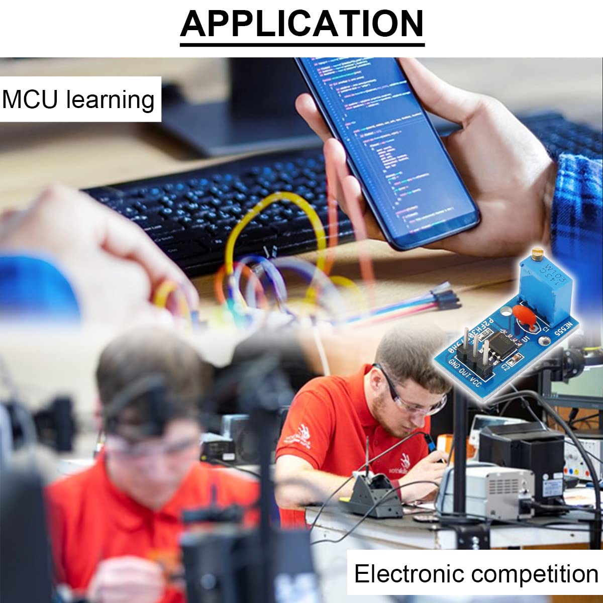
Imej 8.1: Cthamples of applications for the NE555 Pulse Generator Module.
9. Waranti dan Sokongan
This product is manufactured by DAOKAI. Specific warranty details are not provided in the product information. For any product-related inquiries or technical support, please refer to the seller or the platform where the product was purchased. Keep your purchase records for reference.