
1. Pengenalan
This manual provides detailed instructions for the installation, operation, and maintenance of your BooiParts G31T-LM V1.0 Desktop Motherboard. Please read this manual thoroughly before proceeding with installation to ensure proper setup and to prevent damage to the components.
2. Maklumat Keselamatan
- Sentiasa putuskan sambungan bekalan kuasa daripada soket dinding sebelum memasang atau menanggalkan sebarang komponen.
- Wear an anti-static wrist strap or frequently touch a grounded metal object to discharge static electricity before handling the motherboard or other components. Static electricity can damage sensitive electronic parts.
- Kendalikan papan induk di tepinya untuk mengelak daripada menyentuh komponen sensitif.
- Ensure all cables are connected correctly and securely before powering on the system.
- Jangan dedahkan papan induk kepada kelembapan atau suhu yang melampau.
3. Kandungan Pakej
Sahkan bahawa semua item terdapat dalam pakej anda. Jika ada barang yang hilang atau rosak, hubungi peruncit anda.
- BooiParts G31T-LM V1.0 Desktop Motherboard
- I/O Shield (may be included)
- SATA Data Cable (may be included)
- Manual Pengguna (dokumen ini)
4. Produk Lebihview
The BooiParts G31T-LM V1.0 motherboard is designed for Intel LGA 775 processors and supports DDR2 memory. Below are key components and their locations.
Rajah 4.1: Atas view of the BooiParts G31T-LM V1.0 motherboard. This image highlights the central LGA 775 CPU socket, two DDR2 RAM slots to its right, and various expansion slots (PCIe and PCI) below the CPU area. Power connectors and SATA ports are also visible along the edges.

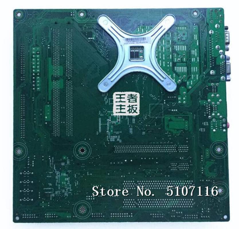
Rajah 4.2: bersudut view of the BooiParts G31T-LM V1.0 motherboard. This perspective provides a clearer view of the rear I/O panel, including PS/2 ports, serial port, VGA output, USB ports, Ethernet port, and audio jacks. Key components like the chipset heatsink and power delivery components are also visible.
4.1 Komponen Utama
- Soket CPU LGA 775: For Intel Core 2 Duo and Pentium D processors.
- Slot DIMM DDR2: Two slots supporting up to 8GB DDR2 memory.
- PCI Express Slot: Untuk kad grafik.
- PCI Slots: For other expansion cards.
- SATA Port: For connecting storage devices.
- Panel I/O Belakang: Includes PS/2 ports, USB ports, VGA, LAN, and audio jacks.
5. Persediaan
5.1 Persediaan
- Ensure your computer case is compatible with Micro-ATX motherboards.
- Gather all necessary components: CPU, CPU cooler, DDR2 RAM, power supply, storage devices, and graphics card (if not using integrated graphics).
5.2 Pemasangan CPU
- Cari soket LGA 775 pada papan induk.
- Lift the load lever and open the CPU socket cover.
- Carefully align the CPU with the socket, ensuring the notches on the CPU match the keys on the socket. Do not force the CPU into place.
- Close the socket cover and push down the load lever until it locks into place.
5.3 Pemasangan Penyejuk CPU
Apply thermal paste to the CPU if not pre-applied on the cooler. Install the CPU cooler according to its manufacturer's instructions, ensuring it is securely fastened and the fan cable is connected to the CPU_FAN header on the motherboard.
5.4 Pemasangan RAM
- Buka klip di kedua-dua hujung slot DIMM DDR2.
- Jajarkan modul RAM dengan slot, pastikan takuk pada modul sepadan dengan kunci dalam slot.
- Tekan ke bawah dengan kuat pada kedua-dua hujung modul RAM sehingga klip terpasang pada tempatnya.
5.5 Motherboard Installation into Case
- Pasang perisai I/O ke dalam bukaan belakang sarung komputer anda.
- Carefully place the motherboard into the case, aligning the screw holes on the motherboard with the standoffs in the case.
- Selamatkan papan induk dengan skru. Jangan terlalu ketat.
5.6 Kuasa Penyambung
- Sambungkan penyambung kuasa ATX 24-pin daripada bekalan kuasa anda ke pengepala yang sepadan pada papan induk.
- Connect the 4-pin ATX 12V power connector (CPU power) to its header near the CPU socket.
5.7 Connecting Storage Devices
Connect your SATA storage devices (HDD/SSD) to the SATA port on the motherboard using a SATA data cable. Connect the power cable from your power supply to the storage device.
5.8 Menyambungkan Penyambung Panel Hadapan
Connect the front panel cables (Power SW, Reset SW, HDD LED, Power LED, USB, Audio) from your case to the corresponding headers on the motherboard. Refer to the motherboard's silkscreen labels for correct pin orientation.
5.9 Menyambung Peranti
Connect your keyboard, mouse, monitor, and other peripherals to the appropriate ports on the rear I/O panel.
6. Arahan Operasi
6.1 Boot-Up Pertama
After completing all connections, turn on your power supply and press the power button on your computer case. The system should power on, and you should see a display on your monitor. If not, refer to the Troubleshooting section.
6.2 Persediaan BIOS/UEFI
During startup, press the designated key (usually DEL or F2) to enter the BIOS/UEFI setup utility. Here you can configure system settings, boot order, and monitor hardware status.
7. Penyelenggaraan
- Pembersihan: Bersihkan habuk dari papan induk dan komponen secara kerap menggunakan udara termampat. Pastikan sistem dimatikan dan dicabut plag sebelum dibersihkan.
- Kemas Kini BIOS: Semak pengeluar weblaman web untuk kemas kini BIOS. Hanya kemas kini BIOS jika perlu dan ikut arahan dengan teliti untuk mengelakkan ketidakstabilan sistem.
- Pengurusan Kabel: Pastikan kabel disalurkan dengan kemas untuk meningkatkan aliran udara dan mengelakkan gangguan.
8. Penyelesaian masalah
8.1 Tiada Kuasa
- Check if the power supply is switched on and properly connected to the motherboard (24-pin and 4-pin connectors).
- Ensure the front panel power switch cable is correctly connected to the motherboard header.
- Uji bekalan kuasa dengan sistem lain atau penguji bekalan kuasa.
8.2 Tiada Paparan
- Verify that the monitor is connected to the correct video output (onboard VGA or discrete graphics card).
- Reseat the RAM modules. Incorrectly seated RAM is a common cause of no display.
- If using a discrete graphics card, ensure it is properly seated in its PCIe slot and has adequate power connected.
- Cuba but dengan hanya satu batang RAM.
8.3 Ketidakstabilan/Ranap Sistem
- Periksa suhu CPU dan GPU. Kepanasan berlebihan boleh menyebabkan ketidakstabilan.
- Pastikan semua pemandu dikemas kini.
- Jalankan alat diagnostik memori untuk memeriksa RAM yang rosak.
- Sahkan bekalan kuasatage adalah mencukupi untuk semua komponen.
9. Spesifikasi
The following table outlines the key specifications for the BooiParts G31T-LM V1.0 Motherboard.
| Ciri | Spesifikasi |
|---|---|
| Jenama | BooiParts |
| Nama Model | G31T-LM V1.0 |
| Soket CPU | LGA 775 |
| Pemproses yang Serasi | Intel Core 2 Duo, Intel Pentium D |
| Jenis Chipset | Intel G31 |
| Teknologi Memori RAM | DDR2 |
| Slot Memori Tersedia | 2 |
| Kapasiti Storan Memori (Maks) | 8 GB |
| Antara Muka Kad Grafik | PCI Express |
| Total SATA Ports | 1 |
| Total PCIe Ports | 2 |
| Jenis Penyambung Kuasa Utama | 24-Pin |
| Peranti Serasi | Komputer Peribadi |
| Nombor Model | T4900V 53Y3282 45C2882 |
10. Waranti dan Sokongan
Untuk maklumat jaminan dan sokongan teknikal, sila rujuk dokumentasi yang disediakan bersama pembelian anda atau hubungi peruncit anda. Simpan bukti pembelian anda untuk tuntutan jaminan.