
1. Pengenalan
The Rakstore EGS002 is a specialized drive board designed for pure sine wave DC-AC inverters. It utilizes the EG8010 digital pure sine wave inverter chip and the IR2110 driver chip to generate a stable, high-quality pure sine wave output. This board is suitable for DIY inverter projects and repairs, providing a reliable control core for converting DC power to AC power with minimal harmonic distortion.
2. Maklumat Keselamatan
Please read and understand all safety instructions before installing or operating the EGS002 drive board. Failure to follow these instructions may result in electric shock, fire, or serious injury.
- Bahaya Elektrik: This board operates with electrical voltages. Always disconnect power before making any connections or adjustments.
- Pemasangan Profesional: Installation should be performed by qualified personnel familiar with electronic circuits and inverter systems.
- Pembumian yang betul: Ensure all components of your inverter system are properly grounded to prevent electrical shock.
- Pengudaraan: Ensure adequate ventilation for the entire inverter system to prevent overheating, especially for power MOSFETs and transformers driven by this board.
- Keserasian Komponen: Use only compatible components (MOSFETs, transformers, capacitors) with this drive board.
- Elakkan Litar pintas: Prevent short circuits during installation and operation.
3. Produk Lebihview
The EGS002 board is a compact and efficient solution for generating pure sine wave AC output. It integrates essential control and drive functionalities onto a single PCB.
Ciri-ciri Utama:
- 5V single power supply operation.
- Fixed frequency output options: 50Hz or 60Hz pure sine wave.
- Adjustable frequency options: 0-100Hz or 0-400Hz pure sine wave.
- External 12MHz crystal oscillator for precise timing.
- PWM carrier frequency of 23.4KHz.
- Integrated EG8010 and IR2110 chips.
Board Components and Dimensions:
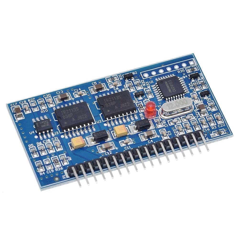
Rajah 1: Atas view of the EGS002 drive board showing key components and overall dimensions. The board measures approximately 61.9mm in length and 32.7mm in width.

Rajah 2: Bahagian atas dari dekat view of the EGS002 board, highlighting the EG8010 chip, IR2110 driver ICs, and the 12MHz crystal oscillator.
4. Persediaan dan Pemasangan
Proper connection of the EGS002 board is crucial for its functionality and the safety of your inverter system. Refer to the pinout diagram below for correct wiring.
Pinout Diagram and Connections:

Rajah 3: Bawah view of the EGS002 board showing the labeled pin headers for various connections.
The board features multiple pin headers (JP1, JP2, JP3, JP4, JP5, JP6, JP7, JP8) for input power, feedback, fan control, and LCD display connections. The main output pins (1LO, 1HO, 2LO, 2HO) are for driving external MOSFETs in a full-bridge configuration.
- Bekalan Kuasa: Connect a stable 5V DC power supply to the designated +5V and GND pins.
- MOSFET Drivers: Connect the 1LO, 1HO, 2LO, 2HO pins to the gate drivers of your external power MOSFETs. Ensure proper isolation and dead-time settings if not handled by the IR2110.
- Feedback (IFB, UFB): These pins are for current and voltage feedback from the inverter output, allowing the EG8010 to regulate the sine wave.
- Fan Control (FANCTR): Connect a fan control circuit here if your inverter requires active cooling.
- LCD Display (LECDEN, LECDCL, LECDDI): These pins are for connecting an optional LCD display to monitor inverter status.
- Frequency Selection Jumpers (JPx): Configure the jumpers (JP1-JP8) according to your desired output frequency (50Hz, 60Hz, or adjustable range). Consult the EG8010 datasheet for specific jumper configurations.
Note: Detailed wiring diagrams for a complete inverter system (including power stage, transformer, and filtering) are beyond the scope of this manual. Refer to the EG8010 datasheet and general inverter design principles for comprehensive system integration.
5. Arahan Operasi
Once the EGS002 drive board is correctly integrated into your inverter system, operation involves applying the DC input power and monitoring the AC output.
- Kuasa Permulaan: After verifying all connections, apply the 5V DC power to the EGS002 board. The board should initialize, and the EG8010 chip will begin generating the SPWM signals.
- System Power-Up: Apply the main DC input voltage to your inverter's power stage (e.g., battery bank). The EGS002 will drive the MOSFETs to produce the AC output.
- Pemilihan Kekerapan: The output frequency (50Hz, 60Hz, or adjustable) is set via jumpers during installation. Ensure this matches your application's requirements.
- Pemantauan: If an LCD display is connected, monitor the output voltage, current, and frequency. Otherwise, use external measurement tools.
- Aplikasi Beban: Gradually apply the AC load to the inverter output. Monitor for stable operation and ensure the inverter's power stage can handle the load.
6. Penyelenggaraan
The EGS002 drive board is a robust electronic component, but proper maintenance can extend its lifespan and ensure reliable operation.
- Jaga kebersihan: Periodically inspect the board for dust and debris. Use compressed air or a soft brush to gently clean the surface.
- Keringkan: Ensure the board is always kept in a dry environment. Moisture can cause short circuits and damage.
- Periksa Sambungan: Regularly check all wiring connections for tightness and corrosion. Loose connections can lead to intermittent operation or damage.
- Keadaan Persekitaran: Kendalikan papan dalam julat suhu dan kelembapan yang ditentukan.
7. Penyelesaian masalah
If you encounter issues with your EGS002 drive board or the inverter system it controls, consider the following troubleshooting steps:
- Tiada Output AC:
- Verify the 5V DC power supply to the EGS002 board is stable and connected correctly.
- Check all connections between the EGS002 and the MOSFET driver stage.
- Ensure the main DC input to the inverter power stage is present and within the correct voltagjulat e.
- Inspect MOSFETs for damage or overheating.
- Incorrect Output Frequency:
- Review the jumper settings on the EGS002 board to ensure they match the desired frequency (50Hz, 60Hz, or adjustable range).
- Check the 12MHz crystal oscillator for proper seating and functionality.
- Unstable or Distorted Sine Wave:
- Check the feedback connections (IFB, UFB) for proper wiring and signal integrity.
- Ensure the output filter components (inductors, capacitors) of your inverter are correctly sized and connected.
- Verify the stability of the 5V power supply to the EGS002.
- Terlalu panas:
- This board itself generates minimal heat. If the board is hot, it may indicate a short circuit or a fault in connected components.
- If the MOSFETs or transformer in your inverter system are overheating, ensure adequate heatsinking and ventilation.
8. Spesifikasi
| Ciri | Spesifikasi |
|---|---|
| Jenama | Rakstore |
| Nama Model | EGS002 |
| Power Source (for board) | 5V Single DC Supply |
| Bentuk Gelombang Output | Gelombang Sinus Tulen |
| Fixed Output Frequency | 50 Hz / 60 Hz (boleh dipilih) |
| Adjustable Output Frequency | 0-100 Hz / 0-400 Hz (selectable) |
| Kekerapan Pembawa PWM | 23.4 KHz |
| Pengayun Kristal | 12 MHz |
| Keluaran Biasa Voltage (of driven inverter) | 120 Volt (AC) |
| Peak Output Power (of driven inverter) | Up to 2000 Watts (system dependent) |
| Kecekapan | High Efficiency (system dependent) |
| Dimensi (L x W) | 61.9mm x 32.7mm |
| Nombor Model | 172426 |
| UPC | 794304728394 |
9. Waranti dan Sokongan
For warranty information and technical support regarding your Rakstore EGS002 Pure Sine Wave Inverter Drive Board, please contact your point of purchase or the manufacturer directly. Keep your purchase receipt as proof of purchase.
This manual provides general guidance. For advanced technical assistance or specific application questions, it is recommended to consult the official datasheets for the EG8010 and IR2110 chips, and seek advice from experienced electronics professionals.