Docooler XUH6362338938855GM
Docooler JINGSHA X99-8D3 Motherboard User Manual
Model: XUH6362338938855GM
1. Pengenalan dan Lebihview
The Docooler JINGSHA X99-8D3 is a high-performance ATX gaming motherboard designed for LGA2011 V3 processors. It features four-channel DDR3 memory support, an M.2 NVME slot for high-speed storage, and multiple PCI-E expansion slots, making it suitable for demanding computing tasks and gaming setups. This manual will guide you through the installation, configuration, and maintenance of your motherboard.
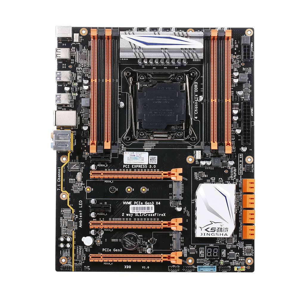
Rajah 1.1: Atas-bawah view of the Docooler JINGSHA X99-8D3 Motherboard, showcasing its layout with CPU socket, RAM slots, and various expansion slots.
2. Ciri-ciri Utama
- M.2 NVME Support: Equipped with an M.2 hard disk port, supporting high-speed PCI-E NVME X4 for optimal operating system and application driver performance.
- Quad-Channel DDR3 Memory: Features 8 DDR3 memory slots across 4 channels, significantly improving capacity and performance, supporting up to 256GB.
- Digital Diagnostic Card: Integrated digital diagnostic card automatically tests hardware devices to ensure proper operation and assist in troubleshooting.
- Multiple PCI-E Expansion Slots: Provides 3 PCI-E expanded slots, configurable as X16/X8 to handle various workloads and multi-GPU setups.
- Pembinaan Tahan Lama: Built with a 10-layer PCB and high-quality capacitors for enhanced stability and heat resistance.

Figure 2.1: Diagram illustrating the six core technologies and features of the motherboard, including 4-channel DDR3*8, M.2 hard disk interface, digital diagnostic card, 7.1 channel audio, SATA3.0*8 interface, and Crossfire support.
3. Kandungan Pakej
Sila sahkan bahawa semua item yang disenaraikan di bawah terdapat dalam pakej anda:
- 1x Docooler JINGSHA X99-8D3 Motherboard
- 1x Kabel SATA
- 1x I/O Baffle (Backplate)
- 1x CPU Fan Board
- A bag of screws
4. Spesifikasi
| Ciri | Spesifikasi |
|---|---|
| Model | X99-8D3 |
| Faktor Bentuk | ATX |
| Graphic Slot | PCIE3.0 16X*3 |
| Kad Rangkaian | Kad Rangkaian Gigabit |
| Saluran Audio | 7.1 Saluran |
| CPU Type Support | LGA2011 V3 (2629V3/2649V3/2669V3/2678V3/2696V3/2676V3/2673V3) |
| Lapisan PCB | 10 Lapisan |
| Slot Memori | DDR3*8 |
| Kapasiti Memori Maks | 256GB |
| Antaramuka SATA | SATA3.0*8, M.2 NVME |
| PS/2 Interface | Tetikus/Papan Kekunci |
| Bekalan Kuasa | 8 PIN*1, 24 PIN*1 |
| Antaramuka USB | USB3.0*6, USB2.0*6 |
| Expanded Interface | PCIE 1X*2, M.2 WIFI*1 |
| Saiz Barang | 30.2 x 24.4 cm (11.89 x 9.61 in) |
| Berat Barang | 930.5g (32.82oz) |

Rajah 4.1: Terperinci view of the motherboard's rear I/O panel, showing PS/2 ports, USB 2.0, USB 3.0, Gigabit Network Port, and 7.1 Audio Ports.
5. Persediaan dan Pemasangan
Sebelum memulakan pemasangan, pastikan sistem anda dimatikan dan dicabut dari salur keluar dinding. Kendalikan papan induk di tepinya untuk mengelakkan nyahcas statik.
5.1 Memasang CPU
- Locate the LGA2011 V3 CPU socket on the motherboard.
- Gently push down the CPU retention lever and swing it open.
- Align the triangular mark on your CPU with the corresponding mark on the socket. Carefully place the CPU into the socket without forcing it.
- Tutup tuil pengekalan untuk mengamankan CPU.
- Sapukan lapisan pes haba yang nipis dan sekata pada bahagian atas CPU.
- Install the CPU cooler according to its manufacturer's instructions, ensuring proper contact and pressure.

Rajah 5.1: Jarak dekat view of the LGA2011 V3 CPU socket on the motherboard, ready for CPU installation.
5.2 Installing RAM Modules
- Buka klip di kedua-dua hujung slot memori DDR3.
- Align the notch on the RAM module with the key in the memory slot.
- Tekan ke bawah dengan kuat pada kedua-dua hujung modul RAM sehingga klip terpasang pada tempatnya, mengunci modul.
- For optimal performance, install RAM modules in matching pairs across the four channels as indicated in the motherboard manual or silkscreen.

Rajah 5.2: View of the eight DDR3 RAM slots on the motherboard, showing their arrangement for quad-channel memory configuration.
5.3 Installing Storage Devices (M.2 NVME & SATA)
- M.2 NVME SSD: Locate the M.2 slot. Insert the M.2 SSD at an angle into the slot, then gently push it down and secure it with the provided screw.
- Pemacu SATA: Connect your SATA SSDs or HDDs to the SATA 3.0 ports using SATA data cables. Ensure the power supply SATA power connectors are also attached to the drives.

Figure 5.3: Close-up of the M.2 interface on the motherboard, highlighting its position and the PCI-E Gen3 X4 connection for high-speed data transfer.
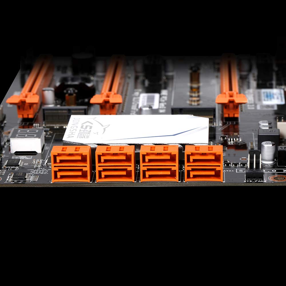
Rajah 5.4: View of the eight orange SATA 3.0 ports on the motherboard, providing ample connectivity for storage devices.
5.4 Menyambung Bekalan Kuasa
- Sambungkan penyambung kuasa ATX 24-pin daripada unit bekalan kuasa (PSU) anda ke port yang sepadan pada papan induk.
- Connect the 8-pin CPU power connector (EPS12V) from your PSU to the 8-pin port near the CPU socket.
5.5 Memasang Kad Pengembangan (PCIe)
- Locate the desired PCI-E 3.0 x16 or x1 slots.
- Tanggalkan penutup slot pengembangan yang sepadan daripada bekas PC anda.
- Align the expansion card with the slot and press down firmly until it is fully seated. Secure the card with a screw to the case.

Rajah 5.5: Bersudut view of the motherboard, highlighting the three PCI Express 3.0 x16 slots and the smaller PCIe x1 slots, ready for graphics cards and other expansion cards.
6. Mengendalikan Motherboard
6.1 But Pertama dan Persediaan BIOS
- Selepas memasang semua komponen, sambungkan monitor, papan kekunci dan tetikus anda.
- Power on your system. During the initial boot sequence, repeatedly press the DEL or F2 key (common for JINGSHA motherboards) to enter the BIOS/UEFI setup utility.
- Dalam BIOS, sahkan bahawa semua komponen yang dipasang (CPU, RAM, storan) dikesan dengan betul.
- Configure boot order to prioritize your operating system installation media (USB drive or DVD).
- Simpan perubahan dan keluar dari BIOS. Sistem akan dimulakan semula.
6.2 Pemasangan Sistem Operasi
Follow the instructions provided with your operating system (e.g., Windows, Linux) to complete the installation process. Ensure you install all necessary drivers for the motherboard's chipsets, network, audio, and other components from the manufacturer's website or included driver disc.
7. Penyelenggaraan
Penyelenggaraan yang betul memastikan jangka hayat dan operasi papan induk anda yang stabil.
- Penyingkiran habuk: Bersihkan habuk dari papan induk dan komponen secara kerap menggunakan udara termampat. Pastikan sistem dimatikan dan dicabut plag sebelum dibersihkan.
- Kemas Kini BIOS: Periodically check the Docooler or JINGSHA official website for BIOS updates. BIOS updates can improve compatibility, stability, and performance. Follow update instructions carefully to avoid damaging the motherboard.
- Kemas Kini Pemandu: Pastikan pemacu sistem anda dikemas kini untuk memastikan prestasi optimum dan keserasian dengan perisian dan perkakasan baharu.
- Keadaan Persekitaran: Kendalikan papan induk dalam persekitaran yang mempunyai pengudaraan yang baik dengan suhu dan kelembapan yang stabil untuk mengelakkan terlalu panas dan degradasi komponen.
8. Penyelesaian masalah
Bahagian ini menangani isu biasa yang mungkin anda hadapi.
8.1 Tiada Kuasa / Tiada But
- Ensure the 24-pin ATX and 8-pin CPU power connectors are securely plugged into the motherboard.
- Check if the power supply unit (PSU) is switched on and connected to a working power outlet.
- Verify that the front panel power button cable is correctly connected to the motherboard's header.
8.2 Tiada Output Paparan
- Ensure your graphics card (if dedicated) is properly seated in its PCI-E slot and has all necessary power cables connected.
- Check that your monitor cable is securely connected to the graphics card or motherboard (if integrated graphics are used, though X99 typically requires a dedicated GPU).
- Try reseating your RAM modules. Incorrectly seated RAM is a common cause of no display.
8.3 POST Code Display (Digital Diagnostic Card)
The motherboard is equipped with a digital diagnostic card (POST code display) that shows a two-digit code during boot-up. Refer to the motherboard's detailed technical documentation (often available on the manufacturer's website) for a list of POST codes and their meanings. This can help pinpoint the exact component causing a boot failure.

Rajah 8.1: Jarak dekat view showing the integrated digital diagnostic card (POST code display) on the motherboard, which assists in identifying hardware issues during boot.
9. Waranti dan Sokongan
For warranty information and technical support, please refer to the documentation provided with your purchase or visit the official Docooler or JINGSHA webtapak. Simpan bukti pembelian anda untuk tuntutan waranti.
Ask a question about this manual
Ask about setup, troubleshooting, compatibility, parts, safety, or missing instructions. Manuals+ will review the question and use this page’s manual context to help answer it.